What’s with big deal with pinion angle?
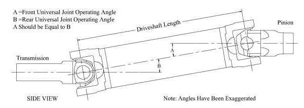
It is a very big deal. In order to keep the driveshaft and U-joints operating in a (more or less) straight line, the pinion angle has to be correct. Typically, the pinion angle is measured between the pinion gear flange and the driveshaft as well as the transmission slip yoke and the driveshaft. And the critical nature of pinion angle is such that it’s important in everything from a low rider to a race car to a lifted 4×4.
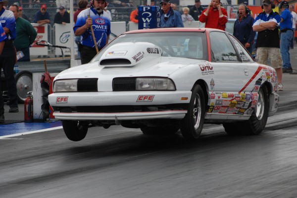
Using a high performance car as an example, consider the rear suspension in the car when it’s under power and it “wraps up.” Here, the pinion is driven upward (out of whack). Rear axle and driveshaft manufacturer Mark Williams points out that the optimal angle for any driveshaft to run at is 1/2 degree, where many vibration and frictional problems are non-existent. In order to minimize power loss and vibration in an offset configuration, the pinion centerline and the transmission centerline need to be parallel. In general, the largest angle for racing applications should be 2 degrees and the centerlines should be parallel within a few 1/10 of a degree. If the chassis has some type of a parallel traction bar system the angles should remain parallel throughout the suspension travel.
“There should be no pinion angle (0-degrees) on acceleration, or vibrations, power loss, and universal joint breakage can result,” said drag race chassis builder Jerry Bickel.
Keep in mind that with suspension movement the operating angle will increase, but should not exceed a few degrees. If the parallelism of the centerlines changes, the U-joints travel at uneven operating velocities, causing vibration (this is the same problem induced by poorly phased end yokes). This vibration is hard to distinguish from an unbalanced driveshaft.
To ensure that the pinion is in the correct location under power, it is typically set nose down static. Some of the most common information (or perhaps misinformation) on setup was derived from the very early years of Mopar racing. The very early Chrysler cars had a very thick spring and were subject to wind up. In an effort to make allowances for this wind up, the pinion was dropped down a few degrees. This was done to keep the center lines running close to parallel when under power. If the car has OEM style rubber suspension bushings, a pinion angle of -3 to -4 degrees is likely more appropriate. This nose-down attitude was originally done in order to compensate for the compression of the rubber bushings.
In order to set the pinion angle on a four-link car with adjustment capability (for example, a drag race four-link), you lengthen or shorten one or both of the upper four-link bars to move down or up. On a triangulated four-link (factory GM or Ford), the upper bars are also used to set the pinion angle (by adjusting both uppers the same direction and same amount). If the vehicle is equipped with leaf springs, then you can use wedge-shaped aluminum shims to move the pinion up or down. The wedges effectively rotate the pinion upward or downward depending on which way the wedge is facing. Summit Racing sells Lakewood wedge kits in two-degree and four-degree versions for passenger cars and a wider selection of sizes for trucks. The shims are designed to sandwich between the rear-end housing perches and the leaf springs. See the Summit Racing catalog for more examples (we can’t list them all here–there are over 150 different examples). You can also buy rear block kits engineered with a taper to move the pinion up or down.
Jerry Bickel also tells us that the pinion angle should be checked and adjusted any time there are changes in the chassis that have an effect upon the ride height or the length and location of the suspension link bars. Jerry’s advice is applicable to other applications too, but prior to setting up the pinion angle in a race car, Bickel points out that four-link instant center is set, the rear-end is aligned, the chassis is at correct ride height, the weight distribution is set, the tire rollout is checked, and the tire pressure is set.
The other thing you should keep in mind when it comes to the driveshaft is critical speed. Critical speed is the speed at which a spinning shaft will become unstable. This is one of the single largest factors in driveshaft selection. When the whirling frequency and the natural frequency coincide, any vibrations will be multiplied–so much that the shaft may self-destruct. Another way to think of this is that if a shaft naturally vibrates at 130 times a second, and one point on the shaft passes through 0 degrees 130 times a second (7,800 rpm) then the shaft has hit a critical speed.
There are several ways to raise the critical speed of a driveshaft. You can make it lighter, stiffer, or increase diameter without increasing weight. This is the reason carbon fiber makes a good driveshaft. It is stiff and light and can be made to any diameter or wall thickness. Aluminum has a higher critical speed compared to steel (same diameter and length shaft) but it is not quite as strong as steel. Steel, with its good strength characteristics, will have a lower critical speed. Because of this, it’s important to check with a driveshaft manufacturer before you decide upon a specific driveshaft for a specific application.
Whether it’s a 16-second low rider, swamp taming four-wheeler, or 8-second door-slammer, getting the pinion angle right is critical when it comes to delivering power to the rear wheels. For a closer look, check out the accompanying illustrations and photos above.


Wayne,
Great article and reiteration how important pinion angle is in a performance vehicle. Having visited many forums and web sites the general consensus for setting up the pinion angle on a traditional setup with the crankshaft center line level or slightly down and the pinion lower than transmission output shaft would be 1/2* to 2* down in a four bar situation. Where the opinions differ is the application in which one has modified to the point where the pinion is higher than the transmission output shaft (illustration 2 shows this) . Say someone tubs their car, lowers it and runs a much larger diameter tire than “normal”. Illustration 5 shows the optimum angle to the drive line under power but how is it possible to get the pinion set to o* in relation to the drive line like illustration 4 without setting the pinion pointing to terra firma and completely throwing off the phase angles in relation to the transmission output shaft which is lower than the pinion? Would illustration 4 not apply to this scenario? Would you set the pinion down 1/2* to 1* ( at A) in illustration 2 which is past 0* under power? My buddies think I am over thinking this but the “want to get this right the first time” in me has questions. Looking forward to some expert input.
Mark Young
Hi Mark. You’ll note Illustration 2 was marked “note: angles have been exaggerated”. It was done that way to simply illustrate operating angles easily. When you build the car, you should take the ride height into consideration first. And ride height includes the tire diameter(s) you intend to run. Then you lay out the height of the engine and transmission (ride height can dictate some or all of it). Jerry Bickel points out that when you’re building a fresh car:
“The engine/transmission might have to be tilted slightly to avoid misalignment of the driveshaft. The crankshaft/transmission centerline (front driveshaft yoke) must point directly at the rear end pinion yoke.”
What this means is you might have to raise the engine and/or angle it slightly in the build to obtain the correct angle.
To make it easier to understand, here are a couple of quotes from two folks I respect immensely: The first is from the late Carroll Smith:
“When a production car is lowered or the rear tire diameter is increased, the angle of the driveshaft universal joint changes. This can result in the universal joint being asked to exceed it’s operational limit, particularly during wheel travel. The fix is to adjust the pinion where it ought to be”
In his book, Race Car Engineering & Mechanics, noted author Paul Van Valkenburgh provides a simple answer to the questions:
“The smoothness, stress and power loss will all be optimized by laying out all joints to have the minimum angular deflection at the suspenion height that corresonds to maximum acceleration”.
Basically, the straighter the shaft points from the transmission pinion to the rear axle pinion, under acceleration, the better off you are.
i always like reading Wayne Scraba information. I have a 1970 Nova that is becoming a Stock Eliminator car (very slowly) and i consider any information from Mr. Scraba that i can get my hands on to be extremely valuable.
Thanks for the article. One thing it doesn’t explain though, is the angle of the engine/transmission in relation to the pinion. Is it placed level so that under power the angles are the same, or down 1-2 degrees to the rear, or something completely different?
The entire idea is to have the operational angles as close to zero as possible when the car is under acceleration. To get there, you often have to work with the back unversal joint only, because it can be difficult (but in some cases, not impossible) to shim the transmission mount, assuming the vehicle has a three piece mount. See the reply to Mark’s question above for more info:
[…] Guide to Setting Pinion Angle As far as the spring perch put the axle in place under the truck withthe spring perch in place but not welded. Bolt up the u bolts snug not necessarily tight. Set the truck down on its own weight and check angles, adjust as needed. Weld perches. At least that would be my stab at it if I were to do it. googletag.cmd.push(function() { googletag.display('div-gpt-ad-13'); }); __________________ 74 F100 dropped 2wd, roller 347 64-73 JBA mustang headers – 6612S Trickflow heads, super victor intake, comp cams Quick Fuel carb T5 transmission, Crown Vic swap All custom fit. […]
DRAG ACCELERATION EXTREME SITUATION. NORMAL STREET DRIVING, FACTORY COMPROMISE. BUILD FOR REQUIREMENTS.
[…] Pinion Angle […]