Just how important is engine mounting in a drag car? Very.
Consider the case of a common rear-wheel drive production line car: Typically, mounts are laid out in a three-point arrangement — two mounts on the side of the cylinder block and one at the very end of the transmission (usually on the tail shaft). In most of these street-driven applications, mounts for both the engine and transmission are composite steel and rubber affairs.
The purpose is to insulate the car from vibrations. Things are different in a racecar. Not only is there no need to isolate the driver from the engine vibration, but there are other critical demands placed on the engine and transmission mounting assembly.
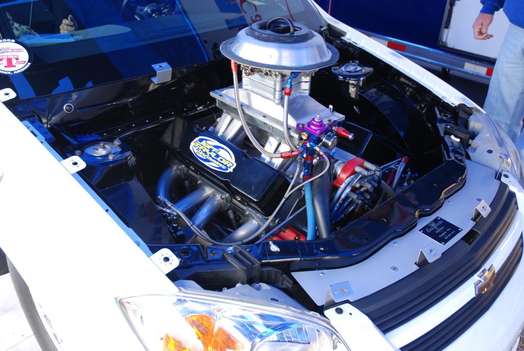
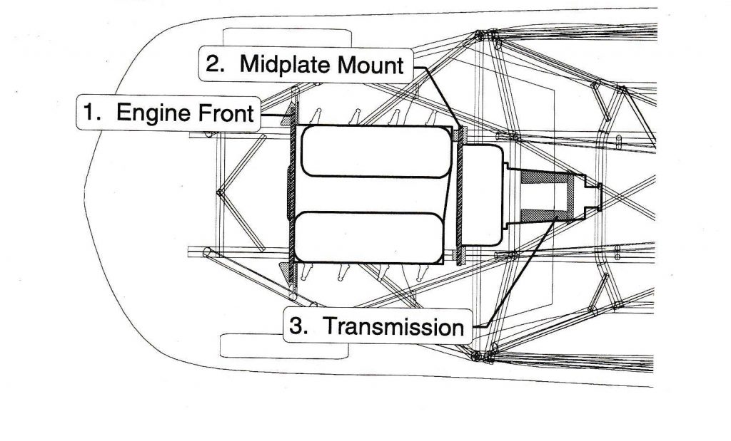
According to Jerry Bickel, it’s not hard to come up with an engine that produces more than 800 ft.-lbs. of torque. A modern racing engine can easily shred the rubber mounts to bits. That’s one reason motor plates are readily available. A motor plate system can mount the engine and transmission in three places. Typically, aluminum plates support the engine at the front while the center, or “midplate,” can be aluminum or steel, and that supports the engine’s rear. The rear engine mount is called the midplate mount because it is between the other two. A steel mount usually supports the transmission (depending upon the gearbox, at the tailshaft or on the sides of the case).
According to Bickel, this system of mounting offers three important advantages for a drag race car:
- The two plates that support the engine are strong. They can handle any amount of torque and vibration produced by the engine.
- The two motor plates span the chassis in critical places, improving the rigidity of the front tubing structure.
- The midplate mount supports both the engine and transmission. Either may be removed without taking time to support the other. This is helpful since it allows you to quickly remove the transmission to service the clutch (or converter), especially in racing where the clutch must be serviced between rounds.
Fair enough, but where exactly do you install a motor plate kit it in the car? (Because in many cases, there are multiple mounting point locations available to you.)
As Bickel notes, the engine must be properly located in the chassis to meet the requirements of the rules and optimize performance. Bickel provides great advice regarding engine location, some of which might surprise you. Below, we’ll take a close look at engine setback, engine/transmission centerline, along with centerline height and engine/transmission angle.
About Engine Setback
When considering engine setback, you should first think like a drag racing sanctioning body.
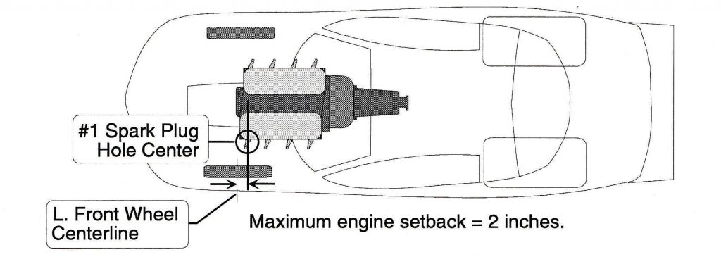
They regularly measure engine setback from the center of the front wheel on the long-wheelbase side (usually the left), to the middle of the front-most spark plug hole.
Long wheelbase side? What’s up with that?
Simple. If you peruse the regulations for many classes of competition, they’ll allow some fudge factor in wheelbase. Sharp chassis builders often stagger the front end as much as possible, hence the “long wheelbase side.” Additionally, all V8 engines have one cylinder bank that is offset slightly forward of the other. On a GM or Mopar, it’s the driver’s side and it’s usually called #1 cylinder in the bank order. Many Ford V8 engines are opposite those of GM and Chrysler.
Before we go any further, Bickel suggests using dummy parts for the initial mockup for a motor plate installation: “Dummy parts are usually damaged components that cannot be repaired. Lightweight aluminum castings are preferred, if you find them. Some chassis builders cut out unneeded internal structure to reduce dummy component weight.”
Basically, use parts that are easy to handle.
Back to setback: Let’s say the legal setback is two inches. To get there, start from the front spark plug hole center on the forward cylinder bank. Drop a plumb bob down from the center of the spark plug hole and then measure to the wheel centerline. If the car is on a chassis jig table, the left front wheel centerline should already be marked. If not you will have to install the left front suspension components in order to locate the wheel (spindle) center. Then you can juggle the engine/transmission assembly to reach the desired setback measurement.
“Engine setback increases the static weight on the rear wheels. Soft-leaving small block or V6 cars should generally have the engine set back to the limit of the rules, but be careful not to exceed the maximum engine setback allowance,” Bickel says. “If the rules allow a maximum setback of four inches, you should locate the engine back only 3.75 inches from the spindle centerline. This will give you some margin for measurement error and assure that the car will pass tech inspection.
“Hard-leaving big block cars create a lot of load transfer and may require less setback to achieve the proper balance at launch. If you go to the full two-inch setback allowance, the car may wheelstand too hard, forcing you to add excessive amounts of ballast to the front end.”
About Engine/Transmission Centerline
Engine setback isn’t the only thing you can juggle with motor plates.
You can also move the engine from side to side. This was done on some production line passenger cars to pick up clearance for things like steering or exhaust.
Case-in-point is a big bock 1967-69 Camaro or ’68-70 Nova. Here, Chevy offset the engine and the transmission to the passenger side. This was done purely for clearance, but it in a racecar it isn’t necessary unless the driver is a particulary large person. Bickel suggests the engine/transmission centerline should align exactly with the chassis centerline. Here’s how he does it:
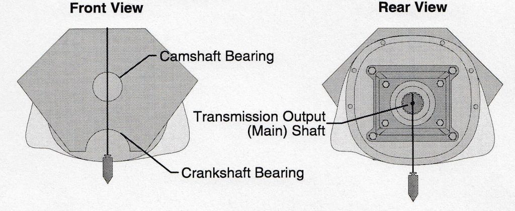
“To measure it, hang a plumb bob at the front of the engine so that the string divides the camshaft and crankshaft bearing holes in half. This represents the front engine/transmission center,” Bickel says. “Hang a second plug bob from the center of the transmission output (main shaft). This represents the rear engine/transmission assembly center. Relocate the engine/transmission assembly as necessary until the plumb bobs align with the chassis centerline.”
About Crankshaft Centerline Distance
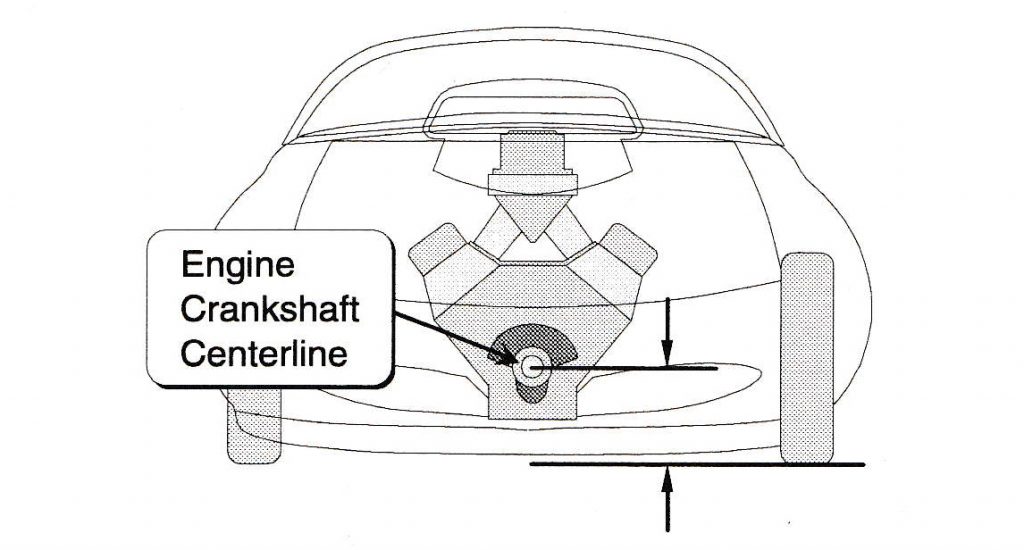
That was easy enough, but one more thing you can change with motor plates is the height of the engine in the chassis. This is called “crankshaft centerline distance.” Bickel tells us to take this measurement from the racing surface to the center of the engine crankshaft front snout.
So what do changes in the crankshaft centerline distance accomplish?
A high crankshaft centerline will raise the vehicle’s center of gravity (CG). As a result, this increases weight transfer to the rear wheels as the car accelerates. A lower crankshaft centerline does just the opposite.
“While there is no set formula for ideal crankshaft centerline, most builders use a measurement of around nine to 12 inches for high horsepower, clutch-type cars,” Bickel says. “Soft-leaving automatic transmission cars may require a higher crankshaft centerline.”
Drag racing sanctioning bodies seldom regulate the crankshaft centerline distance today because body panel dimensions coupled with minimum ground clearance rules limit how creative you can get with crank centerline height.
Bickel’s suggestion here is to be certain the crankshaft centerline distance you use will not require illegal modifications. In other words, take the time to test-fit the front fenders, hood and scoop to the car. It’s also a good idea to measure the engine ground clearance from the oil pan and bellhousing to the racing surface. There’s usually a ground clearance minimum listed in racing league rule books.
About Engine & Transmission Angle
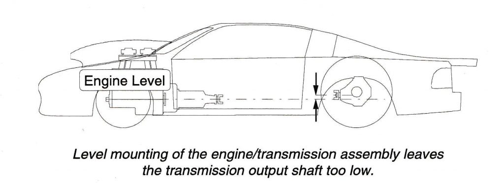
It shouldn’t surprise anyone that the engine and transmission assembly must be tilted slightly to avoid driveshaft misalignment. The crankshaft/transmission centerline must be pointed directly at the pinion yoke, not the centerline of the rear axle, because modern hypoid gears lower the drive pinion in the rear-end housing. (One reason this was done in the 1950s was so that the driveshaft tunnel could be lowered).
In many applications, if the engine is mounted level, the transmission output shaft will be lower than the rear axle pinion. This creates an unnecessary misalignment of the universal joints. The result is obviously driveline vibration, rapid wear and loss of performance. For many racecar applications, if the engine/transmission assembly is tilted slightly, you can aim the transmission output shaft directly at the centerline of the rear end pinion yoke.
“Determine the correct angle by pulling a string or wire from the front crankshaft snout centerline to the rear end pinion yoke,” Bickel says. “Measure the angle with an electronic protractor level. An angle of approximately 1 to 2 degrees is common for many racecars.
“The engine must not be rotated in the chassis. Use an aluminum level across the engine block to be sure the assembly is perfectly level. When installing motor plates, take the time to re-check each measurement to be sure the engine/transmission assembly is properly located in the chassis. Make a checklist of the important measurements and verify each. The list should include engine setback, engine/transmission alignment with the centerline of the chassis, crankshaft centerline distance, engine/transmission angle (tilt) and engine rotation (level).”
As you can see, there’s much more to setback than meets the eye. The key is, using it to your advantage in racecars. It’s there for the taking!

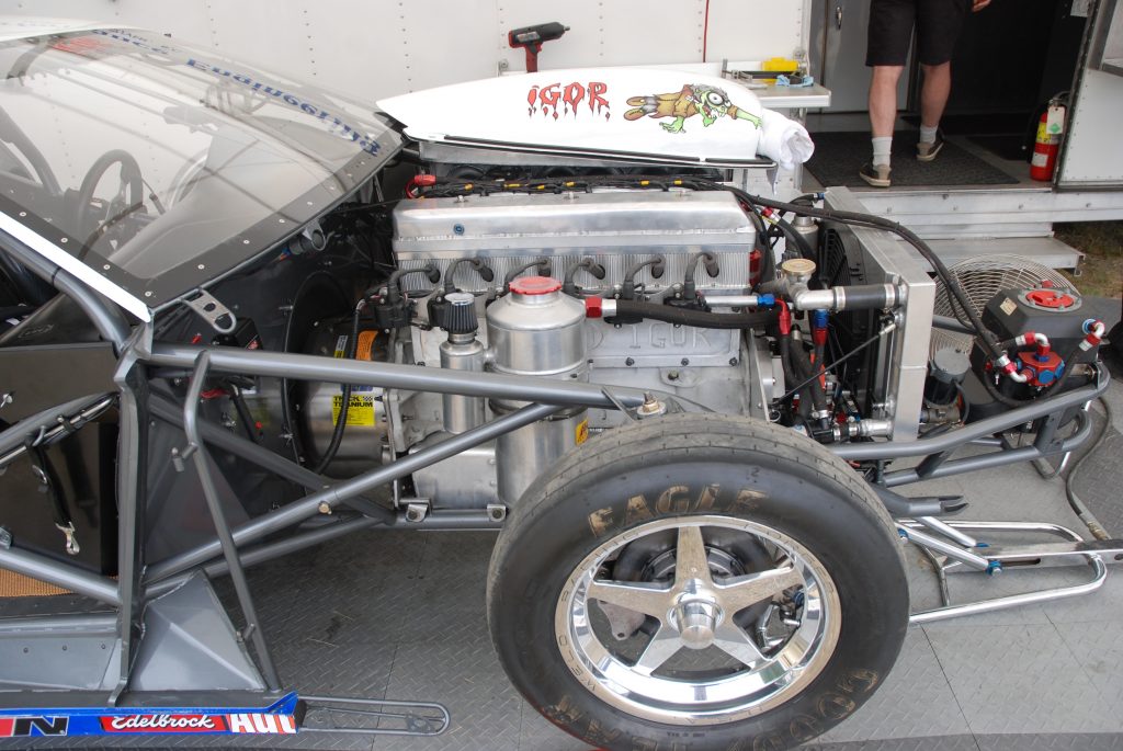
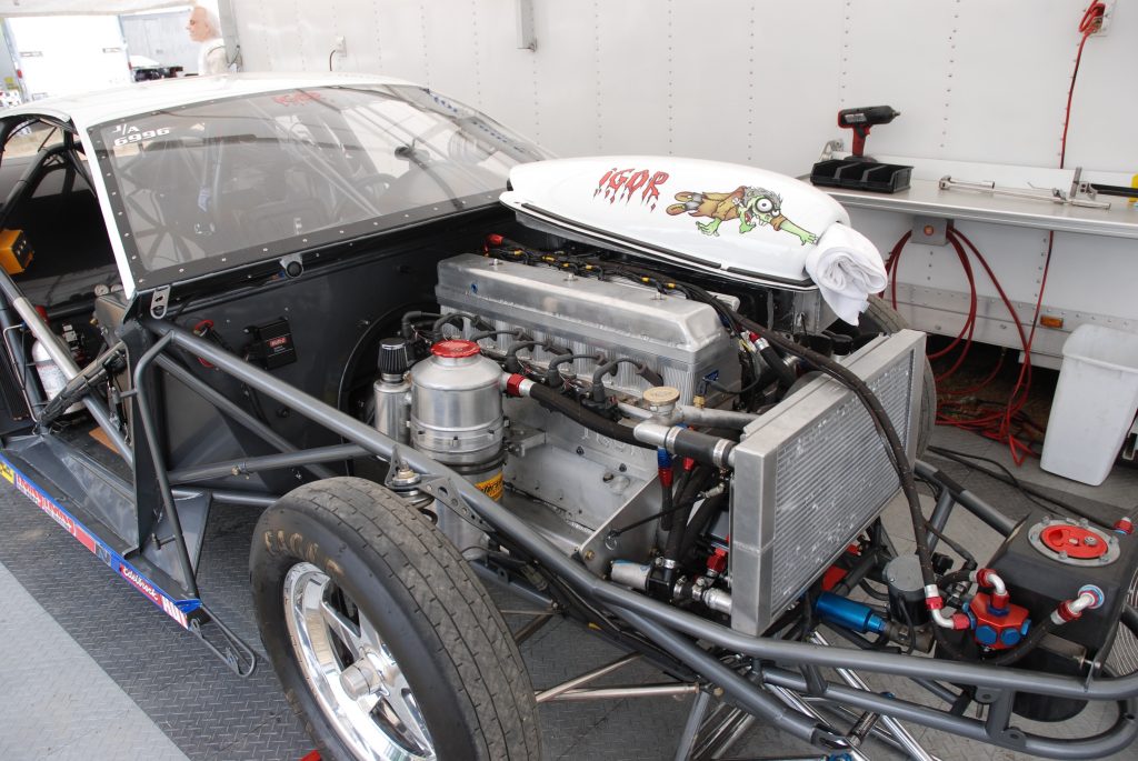
I am building a new rear engine digger now !454 Chev.
Very refreshing to remember old school guys showing me this in the 1970s..
Very educational and informative.
Thank you sirs..
Sir,
Im building a Road Race Alum. BBC. Q: for every inch rewards of the engine ,how much weight is there being transfered to the rear ?
HMF
Westminster Co.
Weight transfer is determined by the height of your center of gravity, wheelbase, weight of the vehicle and acceleration in G’s. Here is the formula W = cogh/wheelbase * weight * acceleration. You can use your camshaft height as an estimate for your cog height. If you need to find your acceleration and have a 60 foot time you can use this formula (32/(.4667*60foottime))/32
If memory serves me correctly, early Camaros also had a staggered wheel base of 5/8 inch.
helloo!!
I have a mustang fox body with 850hp (550 + 300NOS SHOT) install a k-menber Team z motorsport, I leave the engine style factory, with 1 “displaced nose to the driver side.
this is a big problem?
I never knew that an engine is mounted differently for a drag car. My sons is thinking about being a mechanic for race cars. He will be interested to know that the engine is mounted differently.
i have a 79 camaro stock front end putting ing a fab 9 inch the rar is tube frame moly i know a camaro has a 1/2 icnh off set to the passerngr side were can i measure to get the center lin front to back poinion center line 0r can i make the rear end 1/2 inch off lost on trying to get the same axle lenth
A friend has a 1960 T-bird. It’s a street machine, not a race car…but…It has a Boss 429 with an 18″ setback. The seats are sitting in the normal position, as is the dash and steering wheel. Okay, yes, the glove compartment is 3″ Deep…but…
[…] ride height figured out, we still had to determine engine setback, engine height, four link and main hoop placement, seat location, and all the other crucial […]