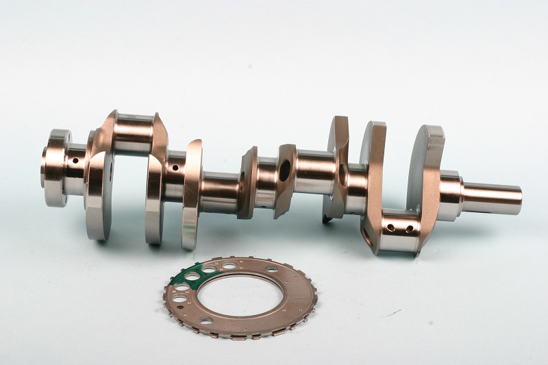
An example of a performance aftermarket LS crank that was purchased without a reluctor wheel installed. (Image/Mike Mavrigian)
Any builder familiar with late model engines knows that an engine’s computer control system monitors both camshaft and crankshaft position in order to achieve correct spark and fuel delivery.
Many crankshafts feature a press-fit toothed timing wheel, referred to as a reluctor wheel.
A magnet sensor mounted stationary in the block is aligned to the wheel and picks up crankshaft position.
GM LS engines feature a toothed reluctor wheel (also called a tone wheel or tone ring), which is press-fit onto the rear of the crankshaft. This toothed wheel is used by the crankshaft position sensor for ignition timing.
There are two styles of wheels:
1. 24-tooth reluctor wheel (24x)
- Gen III LS engines (1996-2007) – includes LS1, LS6, LQ4, LM7 & more
2. 58-tooth reluctor wheel (58x)
- Gen IV LS engines (2005-Present) – includes LS2, LS3, LS7, L76, L99, LY6 & more
…
In most cases, you can identify a Gen III or Gen IV by the location of the camshaft sensor.
Gen III engines featured the cam sensor mounted at the top rear of the block, while Gen IV engines feature the cam sensor mounted onto the timing cover. [Read: How to Identify an LS Engine.]
This is important to note for those who plan to use an aftermarket timing control unit. Some aftermarket companies however, have introduced systems that are compatible with both reluctor wheel types, such as MSD’s LS Series Ignition Control Units.
Either tooth-count wheel can be installed on any LS crank, as long as you have a controller designed for the specific tooth-count.
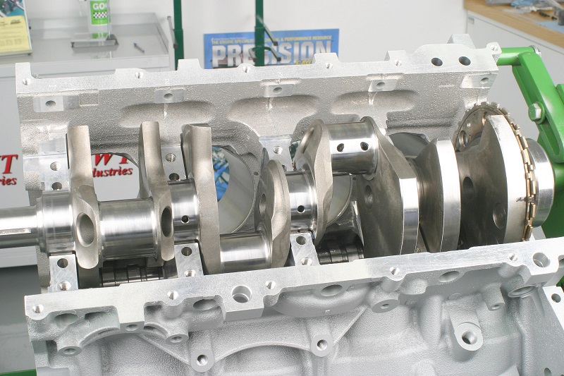
Here’s a view of a 4.000” stroker crank positioned onto the block’s upper main bearings. Notice the reluctor wheel at the far right in this photo. (Image/Mike Mavrigian)
If you’re starting from scratch and have a choice, it’s best to go with a 58-tooth wheel and matching controller for a more accurate timing control.
If you opt to buy an aftermarket performance crankshaft (let’s say you’re building a stroker engine, for example), the crankshaft may or may not include a reluctor wheel.
In either case, pay attention to the number of teeth on the wheel.
NOTE: If you plan to use the factory ECU, you’ll need to stick with the same version (24x or 58x) of wheel that the engine’s controller originally used.
If you plan to use an aftermarket controller, it really doesn’t matter, as long as you buy the correct timing controller that matches your wheel’s number of teeth.
While aftermarket ignition controllers may be applicable to both fuel injected and carbureted engine applications, if you’re prepping an LS engine and plan to go carbureted, you MUST have an ignition controller, and that controller MUST be matched to your choice of reluctor wheel (again, 24x or 58x).
Basically, the OE LS cranks are identical and will install in all LS blocks (variances exist in terms of stroke, and engines that were originally fitted with dry-sump oil systems will feature a longer snout).
Aftermarket cranks are available in a range of strokes to suit your planned build, based on deck height, rod length and piston compression distance.
Regardless, one of the features common to all LS cranks is the need for a toothed reluctor wheel.
The only exception would be for builds that will feature both a carburetor and a distributor. Such conversions from electronically managed ignition to a distributor are less popular, primarily due to the high cost of the parts needed to utilize a distributor (which involves a unique distributor housing, a unique camshaft or cam nose gear extension, a unique water pump, and a new pulley system).
Whether you plan to re-use the OE crankshaft that was included in your new or used engine, or are planning to install an aftermarket performance crankshaft, you may run into a situation where the reluctor wheel needs servicing.
Perhaps the original tone wheel is damaged (missing or bent teet), or maybe you have a crank with a 24-tooth wheel and you want to switch to a 58-tooth wheel. It’s also possible that a new crank that you bought didn’t include a pre-installed wheel.
Most aftermarket crankshaft manufacturers sell LS cranks with the wheel already installed, but it’s possible that you bought a crank where the reluctor wheel is sold separately.
LS Engine Reluctor Wheel Installation Guide
This isn’t a simple matter of hammering the wheel onto the rear of the crank.
The reluctor wheel MUST be indexed correctly to the crank.
If not timed correctly relative to the crank’s rod throws, the engine either won’t fire at all or it will run with such poor timing that it will be worthless.
…
The reluctor wheel (again, also called a timing wheel or tone wheel) is interference-fit onto the rear of the crankshaft, with no key or other registering device.
If you’ve removed the reluctor wheel from a production crank, or if you’re faced with installing a new reluctor wheel onto a new aftermarket crank, where the two components were purchased separately, it’s critical to understand how to properly install the wheel.
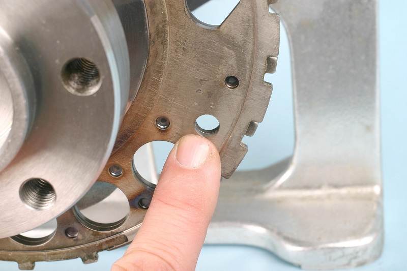
A close-up view of the reluctor wheel’s indexing hole. (Image/Mike Mavrigian)
If you’re removing an original reluctor wheel, first place matchmarks on both the reluctor wheel and crank rear flange.
The position of the wheel is critical.
NOTE: DO NOT attempt to remove the wheel with a puller, since you’ll bend/distort the relatively thin wheel.
Instead, carefully and evenly heat the wheel with a torch to roughly 200 degrees F.
As the wheel expands from the heat, it becomes easy to pull it off by hand (you’ll need to wear heavy welder’s gloves, obviously). This can also be done with a cleaning oven.
The reluctor wheel features a series of teeth that provide crankshaft position signals (via a sensor) to the ECM. The wheel interference-fits to the rear of the crank, immediately forward of the No. 5 main bearing. Typically the wheel features about a 0.007” interference fit.
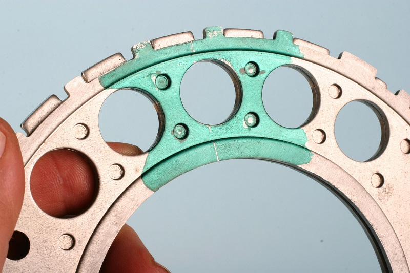
Tone wheels are available in both 24-tooth (LS1/LS6 versions) and 58-tooth (Gen IV/LS2, LS3, LS7, etc.). Selecting the tooth count all depends on your ECU (if you plan to use an OE harness and computer) or an aftermarket timing control module. The two need to match….if you have a 24-tooth wheel, you need a controller for a 24-tooth wheel. The same goes for the 58-tooth wheel (where you’d need a 58-tooth controller). If you already have a controller, then you need to buy the correct reluctor wheel to match up to that controller. (Image/Mike Mavrigian)
Since LS cranks have no keyway or other index point, how do you know where to locate the wheel?
Fortunately, aftermarket indexing tools are available, such as the unit developed by Goodson Shop Supplies that we’re featuring in this article.
They offer a handy and absolutely essential indexing and installation tool for LS reluctor wheel mounting.
The Goodson RRJ-350 Reluctor Ring Jig is comprised of a short steel tube that’s equipped with two indexing pins.
An external tang secures a threaded stud, with the stud tip turned down to an 8mm diameter. This pin engages into the single 8mm indexing hole in the reluctor wheel.
An internal guide pin (a threaded stud with the tip turned down to 11mm) engages into the 11mm blind dowel hole in the crank’s flywheel flange.
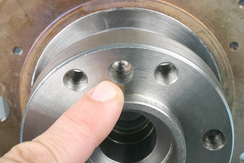
Shown here is the dowel pin hole in the crank’s rear flange. The tool’s internal locating pin fits this hole very precisely. (Image/Mike Mavrigian)
This jig orients the reluctor wheel precisely in the correct timing position.
The two dowel studs feature jam nuts, to allow depth adjustment (you want to make sure that the 8mm dowel passes through the wheel’s 8mm hole, and that the 11mm dowel projects out far enough to engage into the crank flange dowel hole).
For this article, I performed a sample installation.
First, I lightly chamfered the entry hole of the reluctor wheel, and lightly chamfered the edge of the crank’s reluctor wheel flange. The chamfering is advised to ease installation. The instructions also say that the wheel may be pressed onto the crank or heated to 450 degrees F for a slip-on fit. Attempting to cold-press the wheel onto the crank can be tricky since maintaining a square alignment of the wheel to the crank may be difficult. Pre-heating the wheel (resulting in the center hole expanding) makes the job easier to control. I heated the reluctor wheel’s I.D. lip with a torch, slipped the wheel onto the Goodson jig, and the wheel slid onto the crank as easily as a rock drops into water.
My advice: install the ring by pre-heating it, instead of potentially ruining the ring by cold pressing.
Pressing, if not done with a high degree of precision and care, can easily warp the reluctor wheel, which will render it useless.
DO NOT try to force the wheel onto the crank by striking it with a hammer. That’s guaranteed to ruin the wheel.
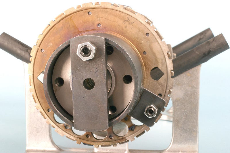
With the reluctor wheel heated and installed to the tool, the tool and reluctor wheel, as an assembly, will slip onto the crank flange. Do not whack the tool or the tone wheel with a hammer. Heating the wheel can be accomplished in a convection oven or by careful use of a torch. (Image/Mike Mavrigian)
CAUTION: The reluctor wheel is made of two plates riveted together. If you’re using a press, and cock it out of alignment and continue to press, the plates can begin to separate. If this happens, you can pinch the plates together with C-clamps and carefully tack-weld it back together at the rivet-hole locations. Just be careful to not create a warp/runout condition.
Again, because the jig indexes to both the wheel and to the crank, misalignment isn’t an issue.
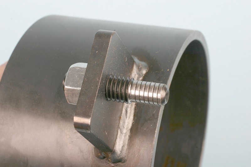
The jig tool’s 8mm locating dowel is shown here. This dowel engages into the reluctor wheel and is located on a welded tang on the outside of the tool body. (Image/Mike Mavrigian)
If you plan to build LS engines, I highly recommend this jig, which takes all of the guesswork and time-consuming measurement out of the equation.
Don’t bother trying to press the reluctor wheel on cold.
Simply heat the ring, seat it onto the jig, and place the jig and wheel onto the crank. With heat and the right tool, it’s easy.
Once the wheel has been installed and allowed to cool, test-fit the crankshaft into the block and carefully inspect to verify that the wheel won’t come into contact with the rear main cap area. Check to make sure that the wheel features no discernable runout, and make sure that it is aligned properly with the crankshaft position sensor, which is located at the left-rear of the block.
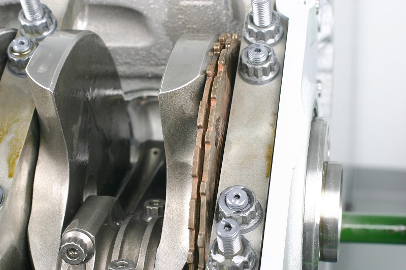
Notice the tight clearance of the reluctor wheel relative to the counterweight and main cap. With all main bearings lubed and main caps fully installed to final torque, carefully rotate the crank to check reluctor wheel runout. If you find more than about 0.002” runout, the wheel is probably bent, in which case you’ll probably need to replace it. (Image/Mike Mavrigian)
…
(A previous version of this article appeared in Engine Professional magazine.)

This is a great and extremely well-written article. question: I have a 2006 GTO and am going to swap the LS2 for the Mast Black Label 630 LS7 Street engine. Mast builds these engines and can do the 24 reluctor so that it will install transparently to my GTO. The stock LS2 is 10.9 compression and the Mast is 11.4 compression. We are stuck with 91 octane here in Arizona and I just read someone say that the 58 reluctor wheel can run fine on the 91 octane but the 24 reluctor cannot. Do they actually have any relation and do you agree with that assessment, please? If so, what do you suggest please? Thank you very much for your consideration of this question.
I meant of course “58 reluctor wheel can run fine at 11.4 compression on 91 octane but the 24 cannot”.
Wow what a in depth well wrote article take there advice the definitely know what the are talking about these rings get damaged more often than you would think and if not cought can make you pull your hair out wondering why the engine won’t run right or not even start !!
My plan is to put a 24X reluctor wheel externally on a 302 Ford and swap it to run on a GM Harness and PCM for tuning reasons.
In relation to clocking the 24X how close does it need to be to work? Are we talking like .002″ or .100″
Working with TDC this can be done, but what is the tolerances?
Thanks
I have a 6.0 Litre iron block around 2000 GMC I had it aligned honed and bored I also purchased a balanced WISECO rotating assembly after the death of my three brothers over the few years it sat in the garage the block has developed rust on the top about an inch in from the edgeand it is about a quarter of an inch deep and about a one inch square area since I need a new block I would rather use a Gen.IV ls iron block the only problem is it’s a 58 relucter wheel blockthe main reason I want the Gen IV is the cyl. are deeper my wiseco pistons will come down in the cyl. to low and cause piston slap so the Gen IV is much better-since I have not bought my MSD wires etc. I think I can stay with the 24 in the Gen.IV block(I do not want to change to a 58 -thanks for your advice
Hi does it matter what reluctor wheel is used when using fly by wire throttle bodies
Not necessarily, the higher reluctor wheel count gives the PCM a closer position count for timing purposes. I’m fairly sure that there are fly by wire vehicles with 24 count reluctor wheels.
Two things: One, what a great article! We do a lot of custom work and I like the later model PCM’s work better for tuning.
Second, I’m doing a custom installation kit for air cooled VW. Could anyone tell me what position that the crankshaft is in when the gap is at the crankshaft sensor? GM Cobalt PCM’s and associated components are pretty easy to come by and I really feel like this system will be a great retrofit for teaching old bugs new tricks.