Could I get your opinion on an engine problem? I spun a rod bearing in my supercharged big-block Chevy. The engine makes big power and has run my ’55 Chevy deep into the 8’s at over 170 mph. I’ve run this engine for a couple of years without problems. All the data log information from the last run looks great but it still lost two rod bearings.
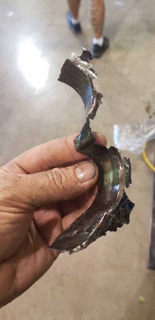
The rod bearings that failed were Numbers 5 and 6. I think #6 failed first and then took out Number 5. My bearing supplier thinks the engine detonated and took the bearings out. The problem is all the other bearings look new. The main bearings on either side of the rods that failed also look great. Even the plugs look good. The EGT temps were all close. I have included some pictures of the bearings. I’ve had a bunch of theories thrown at me but none of them seem like the right answer. Thanks for your help. — D.T.
…
Jeff Smith: This is one of those questions that can cause some sleepless nights trying to figure out what happened.
This case is unusual and required a couple of emails back and forth before we settled on an answer, as his original question didn’t offer all the necessary information.
But his included photos of the good rod bearings, the failed rod bearings, and the good main bearings did offer clues.
We often think the solution has to be exotic and one-off. Sometimes it is. But usually, the simplest explanation is the correct one. Often, the solution is less complex than we thought. That was the case with this failed bearing issue.
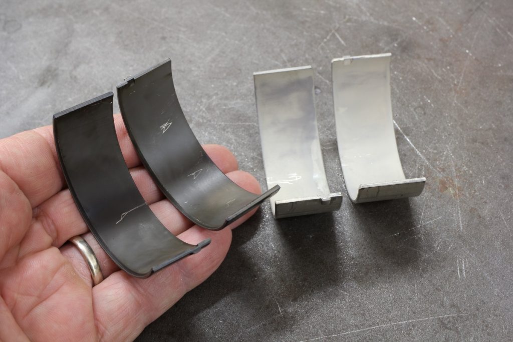
What first clued us in was the difference in appearance between the main bearings and the rod bearings in the photos.

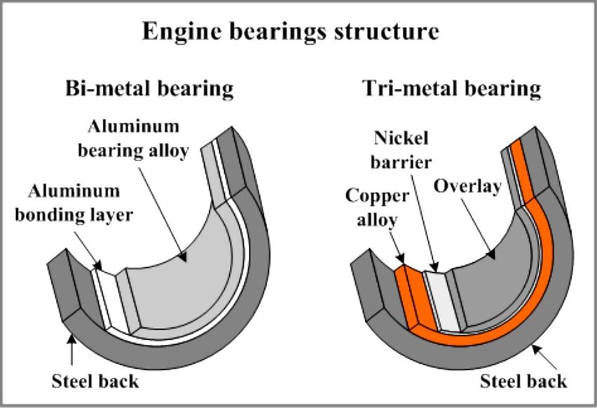
His photo of the rod bearings looked suspiciously like a standard replacement aluminum-silicon bearing material. These are stock bearings made from an alloy formed of aluminum and silicon (Al-Si). The bearing shell is steel, then an aluminum bonding layer is applied followed by the top aluminum alloy material.
According to King Bearings, the 2 to 4 percent silicon is added to both strengthen the material and also to act as a mild abrasive that polishes the journal surface. This is especially helpful with cast iron cranks that, when viewed microscopically, tend to have a very rough surface finish even after final machining.
This aluminum-silicon material is hard and very durable, making it suitable for stock or mild performance engines.
It is not the bearing of choice for a high performance or drag racing engine.
Applications like this with high specific output push the engine to the limit and can exceed the lubrication boundary layer of oil that separates the spinning crank journal from the bearing face. In these situations, a high performance bearing material is necessary. This style bearing starts with a steel backing followed by a copper-alloy layer with a nickel material over that. The top layer is a very thin, very soft overlay material.
This bearing is designed to wear more easily and will accept contact with the spinning crank in short durations. These bearings are intended to wear while the Al-Si style bearing, because it is harder, will tend to peel like an onion. When this peeling occurs, it will quickly contaminate the adjacent bearings and both will quickly fail.
We ran into a similar situation a few years ago when we bolted a centrifugal supercharger on a factory 502 big-block Chevy crate engine.
The engine made 550 horsepower normally aspirated and did so multiple times. But after we added the supercharger and pushed the power to 850 horsepower (a 55-percent power increase!), the crank tweaked slightly and began to peel the Number 2 main bearing.
This engine was fitted with a set of production-style aluminum-silicon bi-metal rod and main bearings. These bearings would have been fine and lasted years at the 550- to 600-hp level. But with the added power from the supercharger, the crank deflected slightly and contacted the Number 2 main bearing. The aluminum bearing peeled off small portions and that junk went right into the adjacent rods, quickly tearing up both the rod and main journals.
Tri-metal bearings like those from Clevite, Speed-Pro, King, and others are designed to be soft so that if the engine is pushed hard and the crankshaft rod or main journal contacts the bearing surface, the softer lead-copper –tin material will quickly deform and wear, preventing or minimizing any serious damage. If the clearance is too tight or the oil film breaks down and allows constant contact, the bearing will still fail. Any bearing will fail in this situation. But in a high rpm, high load point where the crank might just kiss the surface for a micro-second, the bearing will wear slightly with no damage to the crank.
This is the reason why the harder Al-Si bi-metal bearing should not be used in a high-output application.
So the solution is to invest in a quality set of performance tri-metal rod and main bearings.

It sounds like you obviously know how to measure and set bearing clearances so this was just a case of being unaware of the difference in bearing materials. The bi-metal bearings are significantly less expensive, which is a big reason why some enthusiasts prefer them over the tri-metal versions. Now that you know how and why the tri-metal bearings are designed, you can see why they cost more and why they are the best way to go for an extreme performance engine.
At your elevated power level, you might also want to look into using high quality oil intended for race engines. Off-the-shelf oil, even at 20w50 viscosity, does not contain the anti-wear and extreme pressure additives necessary for a competition engine. Race oils like a Valvoline 20w50 or perhaps Driven Racing Oil’s new GP1 20w50 would be a good choice. I’ve seen some testing results on the new GP1 oil and the viscosity remains high even at elevated oil temperatures. Driven’s testing indicates this new oil could offer a slight power increase over other similar viscosity race oils.
We will also assume you had good oil pressure throughout all aspects of engine operation. Again, at these levels, a solid oil pressure delivery of 60 to 75 psi helps maintain that oil cushion between the crankshaft journal and the bearing face. To underscore that idea, we looked up the oil pressure specs for a Top Fuel engine. These nitro-burning monsters are now making an estimated 1,200 to 1,400 hp per cylinder or just a little over 11,000 hp. At idle when cold, these engines will push the oil pressure to 200 psi. Under load at full song, the oil pressure is still between 160 and 170 psi. This is necessary to withstand the enormous load imparted on the rod and main bearings.
It might be useful to also mention coated bearings. I was able to tag along on a test performed by Driven Racing Oil’s Lake Speed, Jr. who was testing the effect of coated vs. non-coated bearings along with a separate variable of synthetic vs conventional oil where the additive packages were exactly the same. The testing was performed on a 383 c.i.d. small-block Chevy at high load and low speed, which is a great way to really load engine bearings.
The test used coated and standard Clevite tri-metal bearings and revealed that the coating significantly improved bearing appearance and reduced wear compared to non-coated bearing. The best combination in terms of reduced wear was coated bearings paired with synthetic oil because the synthetic offers higher thermal stability that maintains its oil film under extreme load and temperature. All three of these companies offer coated bearings for popular performance applications.
If you want to know more about bearings or proper installation and clearances, Mahle-Clevite’s performance bearing catalog is available at their website for download. King Bearings and Federal-Mogul (Speed-Pro) also offer material on their websites that is very informative.

The failure analysis did not show the full set of bearings mains and rods. There are always signs on non failed bearings that help explain the root cause(s). High rpm conrod big end flexing is an important aspect shown by fretting signs on non failed bearing back, and/or at bearing parting lines. Another is debris failure to one rod bearing taking out the other. The crank oilway drilling pattern and intersect angles tell the story here. Centrifugal force tracks the debris to outside of drilling exiting to easiest path it finds first.Odd number or even number rod bearings either side of centre( dead) main, the pattern swaps over there. I.e. rod bearings 1 & 3 then 6 & 8 show debris damage, while rod bearings 2 & 4 and 5 & 7 show lack of lube signs. Adequate oil pressure is essential as said the 10psi/1000rpm has stood test of time. Centrifugal forces feeds rod bearings drawing oil from mains. If oil flow to mains cannot keep up then main bearing scuffing or polishing wear is seen, may only be a polish or touch mark but evidence of a lack of lube problem. Crank flex yet another issue; often shown by off centre or edge loading of bearing surfaces.
I had an Ford 572 do the same thing but actually was 3&7 same position as yours third crank throw back . I didn’t pay real good attention to how piston and rods came out from that throw . But I’m thinking that the rods may have got turned around backward . And the open side not to crank . Ever thing else is engine still looks new like your talking about . Fact melted bearing look just like yours .
This is really good information. Thank you.