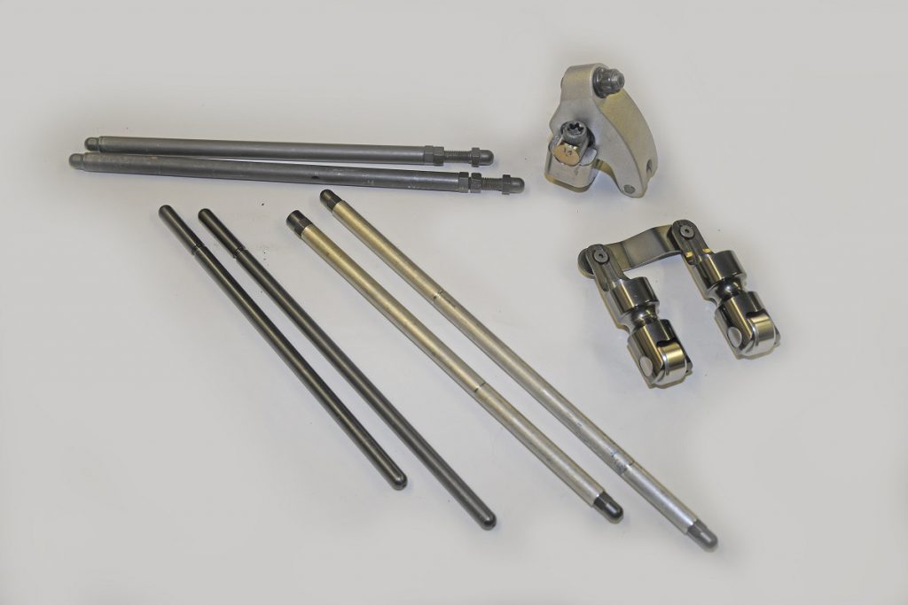
In most cases, the pushrods in your engine drop into a guide plate of some sort in the cylinder head, with the lower end fitting directly into the cup of the lifter. The top end fits into the matching rocker arm.
It’s a simple install.
On the other hand, if the engine is modified with items such as a small base circle camshaft, non-stock cylinder heads, non-stock rocker arm mounting positions, severely milled deck (or head) surfaces, longer-than-stock valves, changes in pushrod seat height in the lifter, the use of valve lash caps, and other factors, you must establish the correct pushrod length.
Even in a normal situation (where the geometry hasn’t changed due to the factors mentioned above), the tip of the rocker arm tends to sweep across the tip of the valve. If the geometry has changed, and the pushrod length isn’t optimized, the amount of movement the rocker sees across the valve tip is considerable.
In order to properly check the geometry and to establish correct pushrod length, you’ll need a checking pushrod.
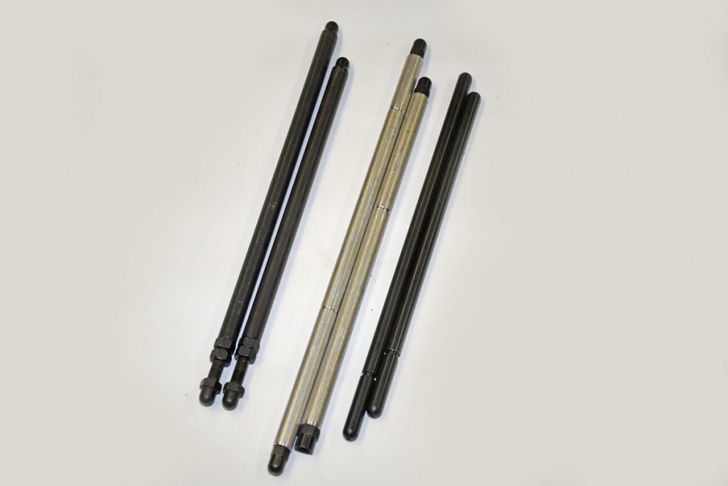
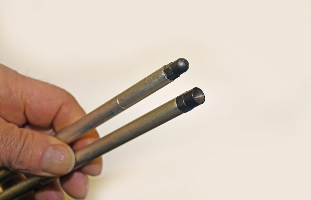
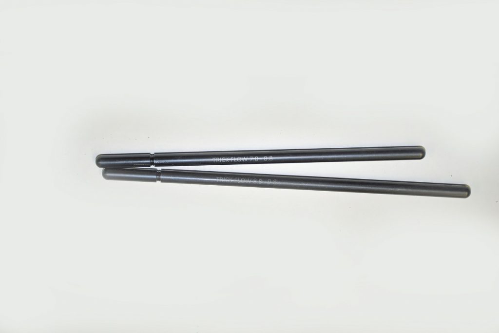
There are several available. We have a set from Crane Cams, two from Jesel, and one from Trick Flow Specialties.
The checking process goes like this (and keep in mind this is the CliffsNotes shortened version):
First, color the top of the valve tip with a marker.
Rotate the crank until the lifter is on the base circle of the cam (opposite full lift). Install an adjustable checking pushrod and then adjust the rocker until you reach zero lash.
Roll the rocker tip across the valve tip (according to the folks from Jesel, you should never turn the engine over with a checking pushrod in place — they’re definitely not strong enough to withstand valve spring pressure).
This will provide you with a witness mark on the valve tip. Examine the position of the mark and re-adjust the pushrod length until the witness mark on the valve tip is approximately one-third of the distance toward the intake side from centerline.
This will generate a close approximation of the ideal pushrod length for street engines.
For a race engine, the ideal pushrod length will have the least amount of travel across the valve tip.
As a result, you’ll have to perform more trial and error (shortening or lengthening the adjustable pushrod) until the sweep across the valve tip is minimized. Trick Flow notes that as a general rule, longer pushrods will decrease rocker arm tip travel.
Obviously, to get the job done, you’ll need at least one of the adjustable ‘checking’ pushrods mentioned previously. With the Jesel and Crane Cams checking pushrods, you should measure the final length of the pushrod with a caliper (and in most cases, it will be a long one) to determine the overall length.
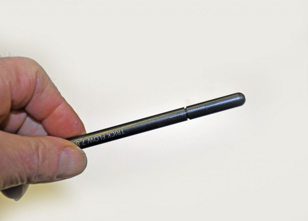
On the other hand, the Trick Flow pushrod checking tools do not require a long caliper.
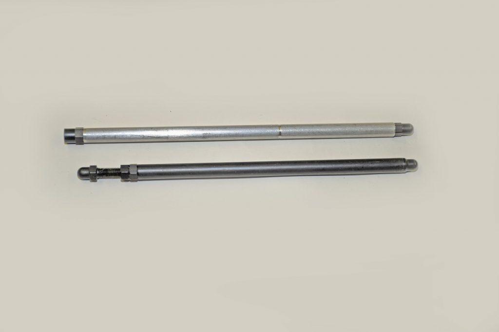
Each of the Trick Flow checkers is marked with a laser-etched alignment line. Each full rotation of the adjustable pushrod represents 0.050-inch.
For example, if you have an 8.800-inch checking pushrod that is fully screwed together and you turn it out one revolution for your setup, then the correct pushrod is 8.850 inches (the standard 8.800-inches + 0.050 = 8.850-inches).
Each of the Trick Flow checkers are manufactured from high-quality steel alloy with a durable black oxide coating for a lifetime worth of pushrod length checks.
They are available in versions with ball tips or cup tips, and in ranges from 5.800 in. to 12.800 inches.
NOTE: If you have a canted valve engine (for example, a big block Chevy), you’ll need two checking pushrods — one for the intake side and one for the exhaust.
As you can see, it’s pretty easy to check and then establish proper pushrod length — especially if you have the right tools in your arsenal. For a closer look, check out the accompanying photos:


“According to the folks from Jesel, you should never turn the engine over with a checking pushrod in place — they’re definitely not strong enough to withstand valve spring pressure.”
Correct, but if you use a low-tension test spring, it’ll be perfectly fine.
The folks from Jesel need to redesign their pushrod if theirs is the only one that can’t handle high pressure springs. Don’t tell me how to adjust for their deficiencies, fix the problem.
As it’s stated, some parts of this procedure may be confusing to some. It says to roll the rocker over the valve stem after installing it and the checking pushrod then cautions against using the checking pushrod when turning the engine with heavy valve springs. Later, it says to move the rocker side to side to create a single witness mark. For both street and high performance engines it’s best to rotate the engine through at least one complete valve cycle to determine not only where the witness mark is but also its width (referenced from the intake side to exhaust side of the valve stem). Generally, checking pushrods are not intended to be operated with heavy valve springs, just to determine pushrod length for proper valvetrain geometry. Rotating an engine with checking pushrods in conjunction with light checking springs would certainly work to arrive at a valve stem sweep witness mark, but might not reflect the actual sweep mark characteristics as would show up when applying (especially) high spring loads. I prefer rotating an engine through a full cycle with a service pushrod and the intended spring and assess the witness mark’s location and width and work from there. Just my opinion. There’s a bunch of ways to do this stuff.
For really accurate testing, a solid lifter should be used.
Hyd lifter can not be trusted on a cold engine. The lifter might have bled down giving false readings.
[…] the process for establishing pushrod length has been covered in other places so we won’t get into that here. But you will need shorter […]