I’m assembling a stout 383ci small block Chevy with a 250 degrees at 0.050 inch duration mechanical roller camshaft. The pistons have a small dome and before I finish assembling this engine I’m wondering about piston to valve clearance. The cam has 0.550 inch valve lift. I was going to do the clay method to check clearance but this seems kinda crude. Is there a better way to check this clearance that’s more accurate?
T.M.
***
The clay method you refer to is the time-honored procedure—but yes there is a more accurate way to check this that also allows you to see when all that occurs.
Many enthusiasts think that the valve to piston clearance is tightest during maximum valve lift, but this is not the case.
The valves come closest to the pistons during the overlap period when the piston is near Top Dead Center (TDC). As the piston approaches the top of its travel, the exhaust valve is closing and the intake valve is just beginning to open. In nearly all cases, the exhaust valve is closest to the piston around 10 degrees Before Top Dead Center (BTDC). Because the intake valve is just beginning to open, it will chase the piston down the bore with it being the closest roughly 10 degrees After Top Dead Center (ATDC).
This means that the closing point of the exhaust valve and the opening point of the intake valve are the critical positions regarding piston-to-valve (P to V) clearance. Let’s run through how to check this clearance.
How to Check Piston-to-Valve Clearance
To perform this test, you will need a degree wheel on the crankshaft along with a dial indicator and a magnetic base. The first step is to set an accurate top dead center location for the degree wheel. This is a critical step since if the TDC location is not accurate your testing may not be precise. You will also need a way to turn the crank with the degree wheel. We like to use a professional crank snout tool that mounts the degree wheel and also offers a convenient way to turn the crank.
Tools Used
- Camshaft Degree Wheel
- Dial Indicator
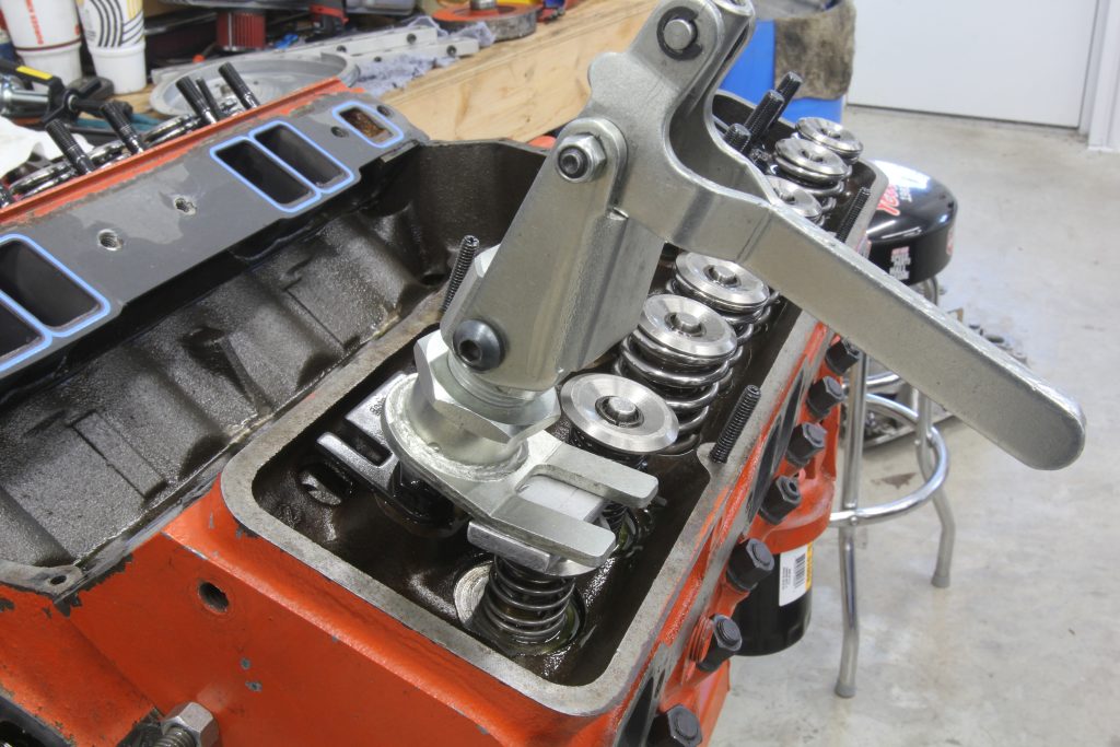
- Summit Racing On-Head Valvespring Compressor Tool – SUM-906784
- Proform Lightweight Valve Checking Springs, Pair – PRO-66793
With the tools at hand, remember that you must first verify that the camshaft is installed properly by degreeing the camshaft. So first make sure the cam is installed where you want it. This is generally done by using the intake centerline method. We won’t go into that as this answer is already lengthy.
Race engine builders will tell you that the best way to check P to V is to use the actual springs, pushrods, and rockers that you will be using when running the engine. Their procedure is as follows.

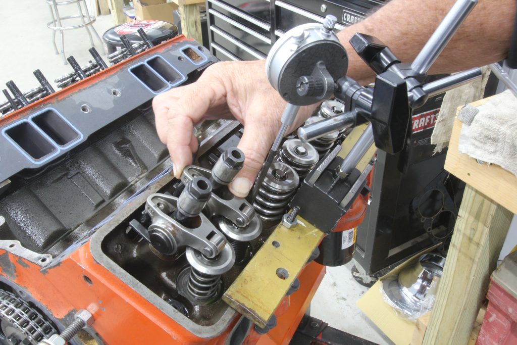
Place the engine at 10 degrees BTDC and position the dial indicator on the exhaust valve retainer. Now compress the valve with a lever tool to measure the distance the valve travels. This will be the clearance between the exhaust valve and the piston. The clearance spec varies with different engine builders but 0.100 inch is a commonly accepted number.
Now place the dial indicator probe on the intake retainer and move the piston to 10 degrees ATDC and repeat the process of pushing the valve against real spring pressure. This spec can be a little bit tighter perhaps to 0.080 inch since the valve is chasing the piston down the cylinder.
This process requires some serious leverage to compress a spring that might have 400 pounds or more of load. We prefer to remove the normal springs and replace them with light duty checking springs that makes this process much easier. Now you can easily depress the valve against that light spring and record the clearance. We check at 2 degrees on either side of the exhaust and intake positions of 10 degrees BTDC and ATDC just to make sure.

Methods for Adjusting Piston-to-Valve Clearance
Once you’ve found the P to V clearances, if one valve is too tight there are changes you can make without having to machine the pistons to increase valve pocket depth. Let’s look at two scenarios.
The first is that the intake P to V is too tight at perhaps 0.070 inch. One quick change would be to retard the cam timing by two degrees and then re-check the P to V.
Retarding the cam delays the intake and exhaust valve opening and closing points. In this situation, by opening the intake valve later, this increases the intake valve clearance to the piston. However, this simultaneously tightens the exhaust P to V so anytime the cam is moved you must check both the intake and exhaust to ensure the clearances are adequate.
The opposite situation where the exhaust P to V is too tight would be to advance the cam. When the exhaust valve P to V is too tight, advancing the cam will improve the exhaust valve clearance but also tighten the intake side.
Other Factors to Consider
There are a couple of things to keep in mind when checking the P to V. With a mechanical cam, you should include the valve lash. When using checking springs we sometimes set the lash at zero to increase the lift at the checking point. This way if we have proper clearance with zero lash, then we will have more than enough with let’s say 0.018 inch lash since valve lift will be greater at all points with zero lash. Of course you can also check P to V with the lash to be absolutely accurate.
If you are using a hydraulic lifter camshaft, it’s best to use a mechanical lifter to check these clearances but also make sure the pushrod cup is in the same location on the mechanical lifter as with the hydraulic. This way it does not change the valvetrain geometry. Using a mechanical lifter will prevent any problems with the hydraulic lifter piston depressing and creating inaccurate measurements.
Also, remember that using checking springs will not produce any deflection in the valvetrain. With the actual valvesprings in place, there could be some minor deflection in the components that could increase the P to V clearance. For example, on a recent small block with big double springs with 600 pounds of force, we saw 0.014 inch of deflection in the valvetrain at max lift even with a stud girdle. With lower spring rates, the deflection will be much less.

Comments