You can check out the other installments in this series here:
- Overland Cruiser (Part 1): Building & Outfitting for Adventure Travel
- Overland Cruiser (Part 2): Tooling Up and Tearing Down
Going Shop-Ping
Toyota Land Cruisers may have a cult following, but most of the faithful wrench their own. And when it comes to older Cruisers, there aren’t a lot of shops out there that work these vehicles on a regular basis anyway. That includes the local dealership, which mostly works on newer vehicles—and comes with a $150-an-hour price tag. Heck, you can almost buy new head bolts for that. (No, just kidding; not even close—not at the dealership, anyway. Try Amayama instead; see below.) The few shops that do specialize in Cruisers and Cruiser engines tend to be hundreds of miles apart, and develop loyal followings.
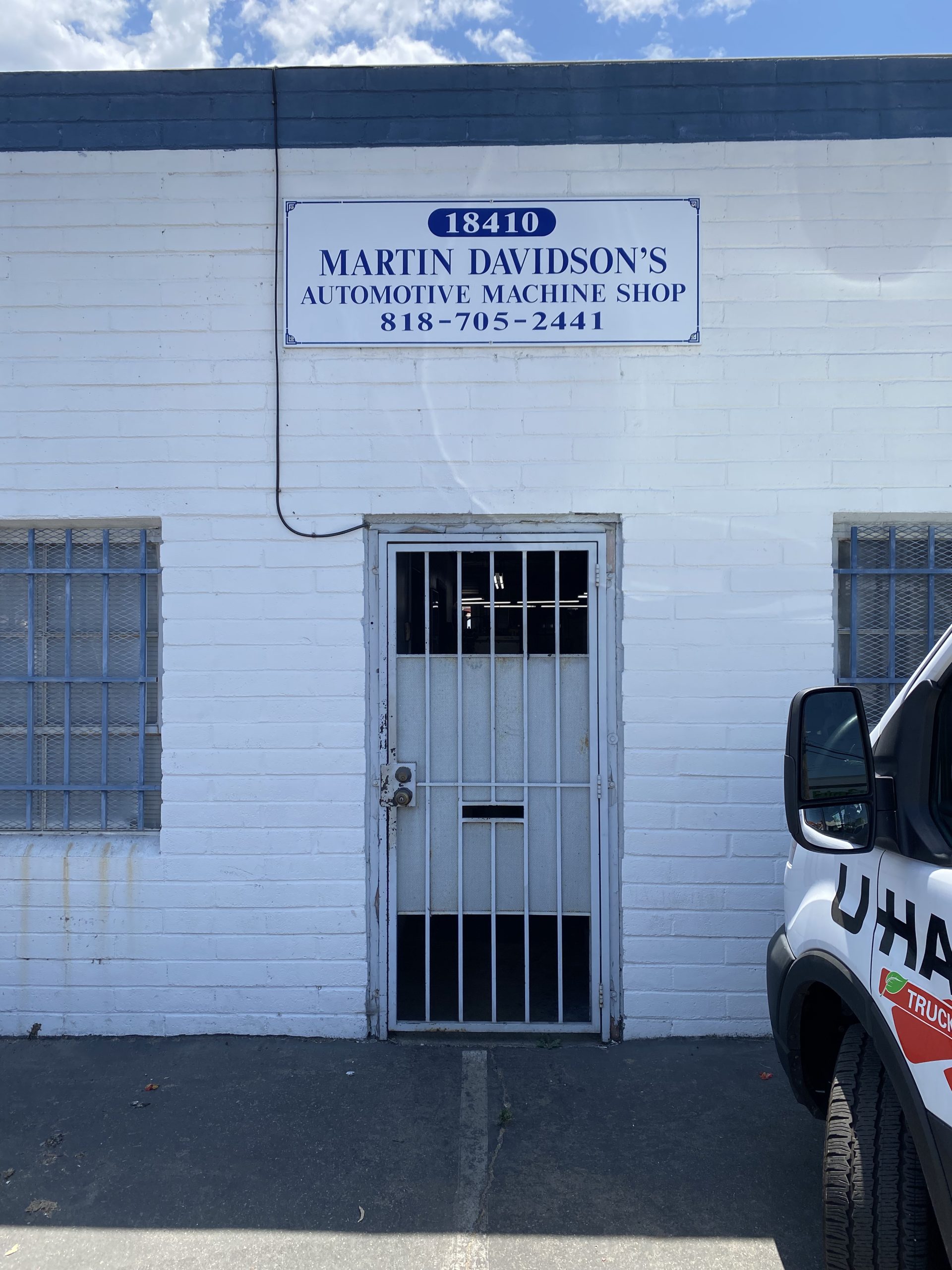
In Los Angeles, California, the go-to place for engine work you can’t do at home is Martin Davidson’s Automotive Machine Shop in Reseda. They’ve been machining and building (and rebuilding) engines for six generations of Land Cruisers. Dealers and other shops send work out to them. Kyle Williamson worked at MD for ten years before buying the place, and has put in another eight years since. Among Cruiserheads, the shop’s reputation is legendary. So of course that’s where we went.
Final Teardown
Once in the shop, teardown work begins…
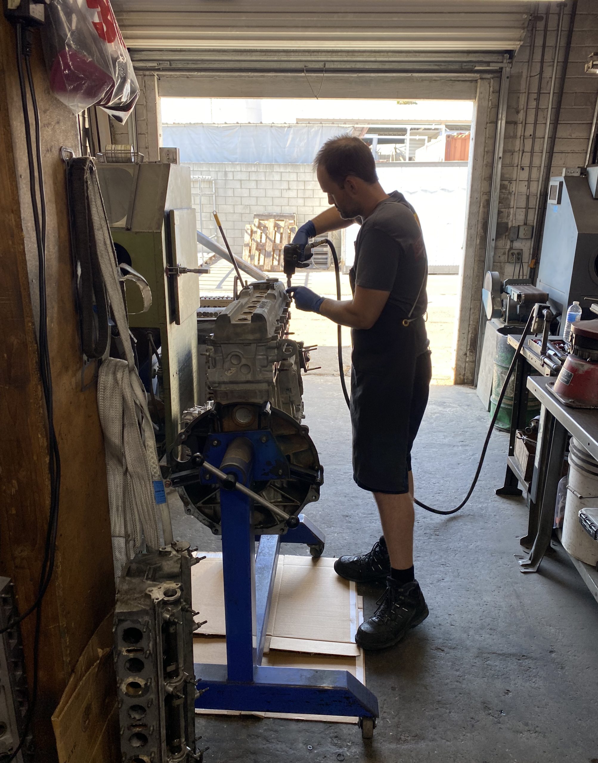
Things go smoothly, with two exceptions. Let’s cover those first, so you know where to expect trouble (maybe).
The first issue involves the small JIS-head screws that hold the oil pump cover in place. These screws have a reputation for being difficult, with the heads often stripping out or breaking off. The truth is, this is usually because people try to remove them with Phillips instead of JIS (Japanese Industrial Standard) screwdrivers, and the bit never fully seats. Plus, the cover itself is aluminum, so you can’t beat up on it too much.
The preferred way to extract is using a manual impact driver with a JIS bit. The kind that turns when you hit the top with a hammer, ensuring a good, deep grip. In our case, we get a good, deep grip all right—so much so that one of the tiny screw heads snaps off, and the rest of it has to be drilled out. (We’ll be replacing all seven with Allen-head versions; the spec is M6-1.0x12mm.)
Once that’s done, we take a look at the oil pump, which is a dead-simple design and likely good for another 250k miles (or more).
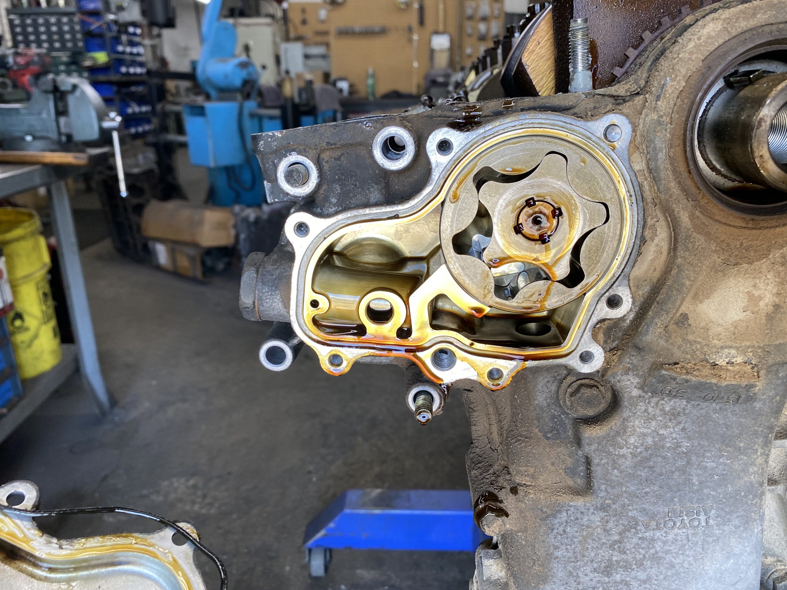
While we’re in here, a word about the oil pump bushing. This part will dissolve if your engine is hot-tanked, unless the shop uses a kinder, gentler cleaning agent. The good news is, this part is still available new from Toyota. The bad news is, it’s free—and factory-installed—when you buy a new block. The part is not sold separately. Fortunately, it’s not a heavy-wear item, and if you go with the kindler-gentler tanking method, you may be able to reuse it. Have your machinist inspect and measure the bushing and the oil pump shaft, and see what shakes out. Otherwise, there’s an aftermarket version available from Landtank Products. Kyle typically has them on-hand as well. Our block needs to be acid-dipped, so we’ll have to replace the bushing.
The larger complication is The Battle of the Bolt.
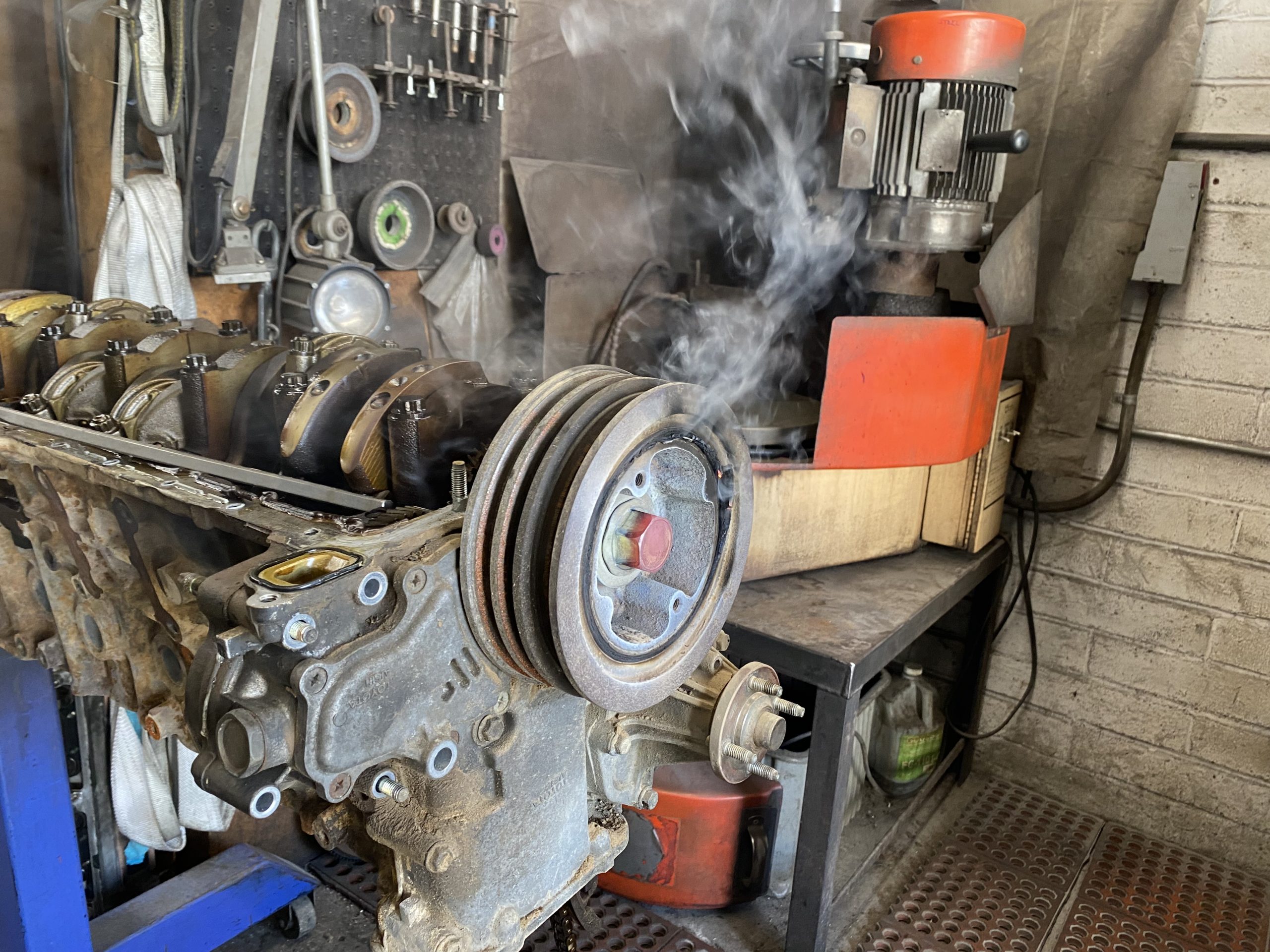
The notoriously hard-to-remove 1FZ crank bolt proves…notoriously hard to remove. Kyle hits it with his usual impact wrench, which never met a crank bolt it couldn’t move. Until now.
Next up: a two-foot breaker bar.
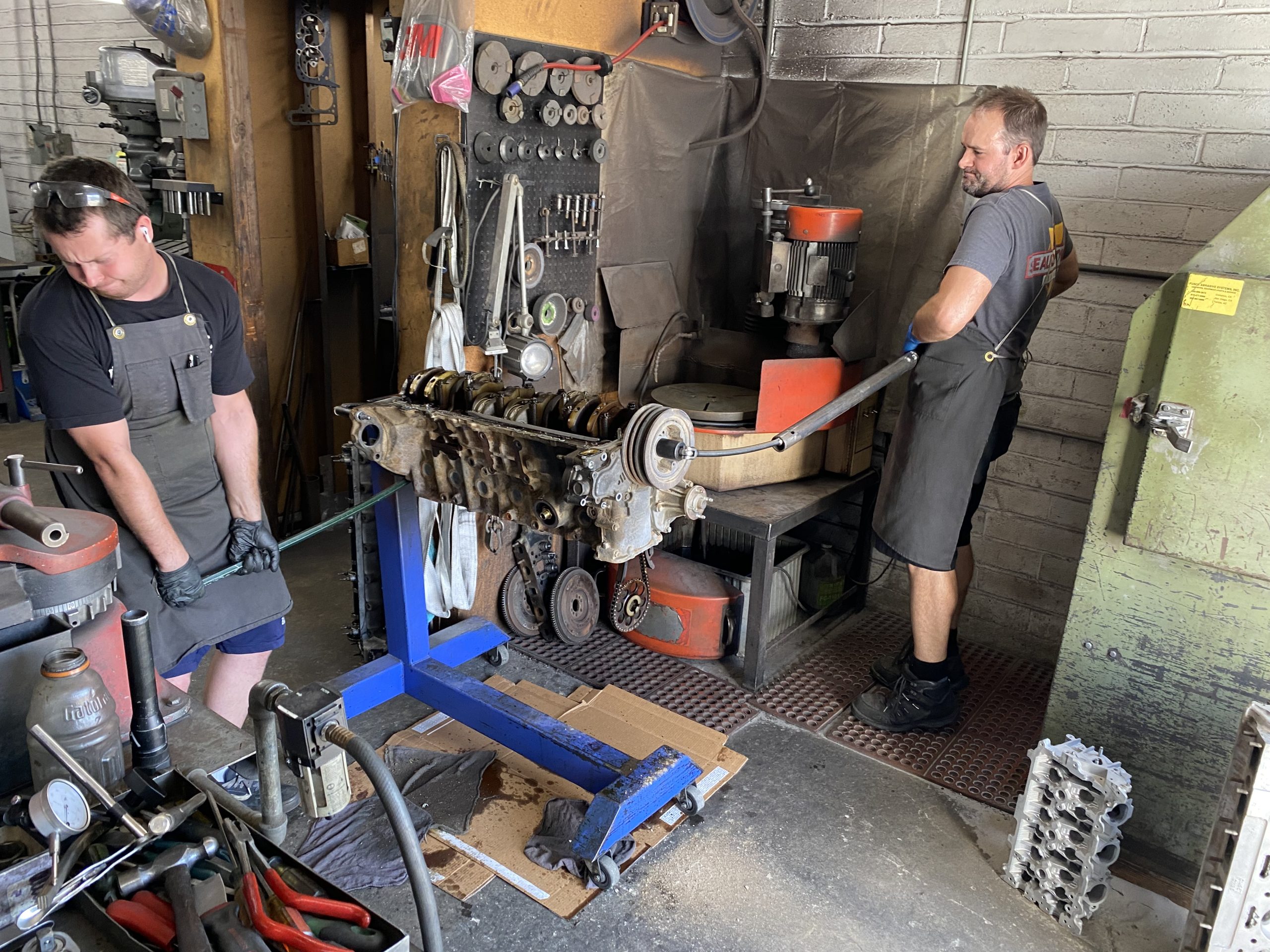
Nada. Two-foot breaker bar with four-foot pipe-handle. Zippo—unless you count the crank moving. Kyle chocks the crank and calls in reinforcements; shop worker Jake keeps the block in place with a pry bar while Kyle cranks on the pipe-handled breaker bar, which bows impressively but does not snap. The pry bar bows too.
The bolt remains unmoved.
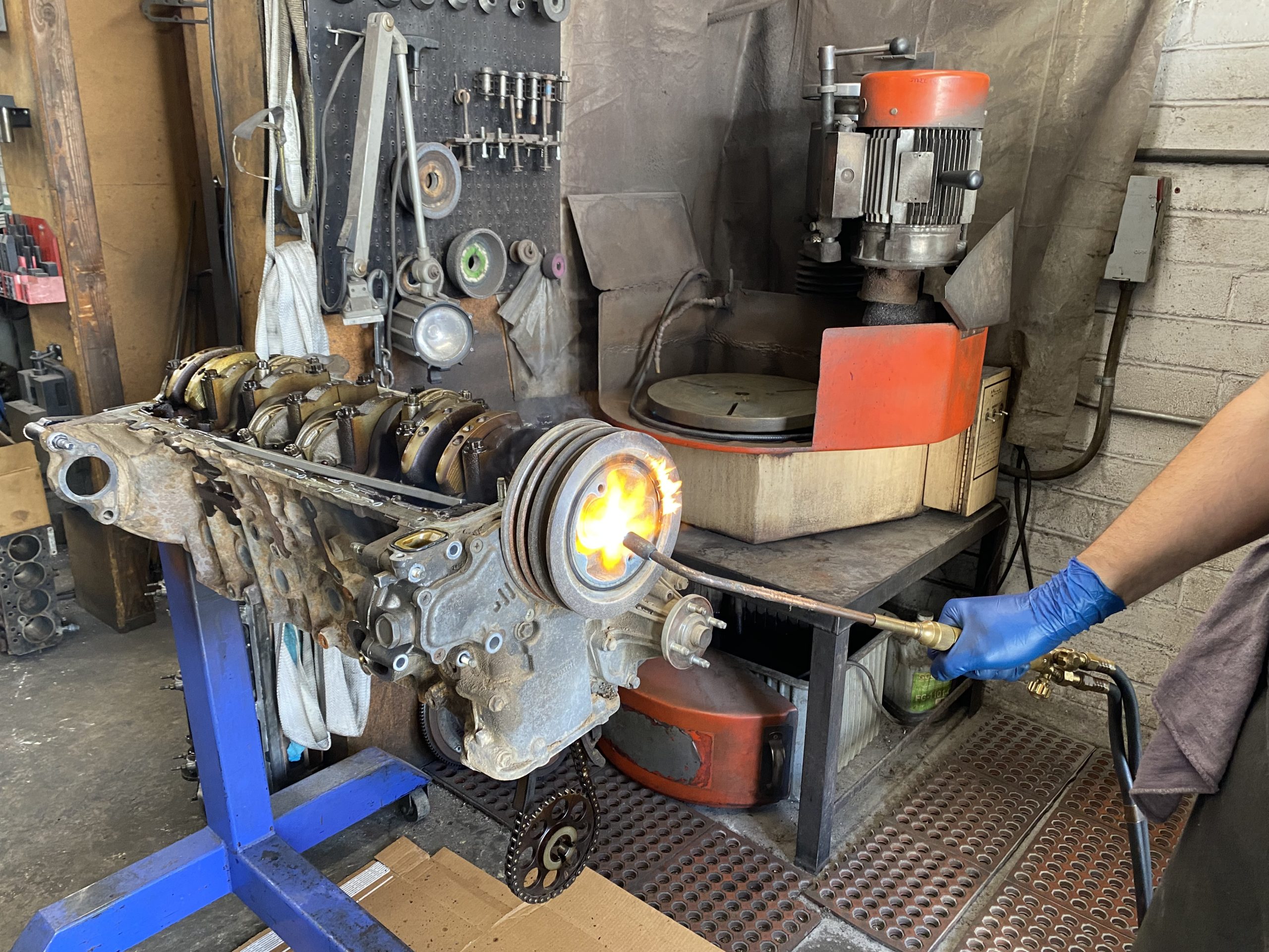
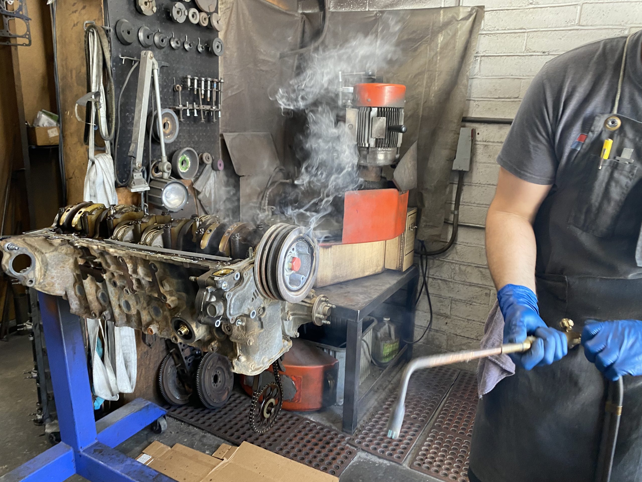
This is followed by a love-tap with a rather large hammer-and punch, and three torch-and-impact wrench sessions, during which the rubber in the balancer catches fire and the crank bolt glows magma-orange. The shop fills with the stench of fire and brimstone. (Well, okay: burning metal and rubber.) And—finally—the crank bolt yields.

About these bolts… The typical DIY technique (with the engine still in-place) is to lash a ¾-inch (minimum) breaker bar to the inside of the PS frame, cover it up to prevent shrapnel (in case the bar snaps), disconnect the coil and bump the starter. This makes it easy to loosen the bolt. It also makes it easy to damage the flex plate or starter, or snap the bolt if it’s on too tight. Most of the time it goes okay.
There’s also the chain/ratchet-strap method, but that can shear the rubber in the balancer. A third option is the custom-made “OTRAMM Crank Pulley Tool” from 717Cruiser on Etsy. This allows you to keep the crank from turning while you loosen the bolt with a very long-handled (and very thick) breaker bar; 3/4- or 1-inch recommended.
When you’re changing the main seal, this is just the thing.
Inspection
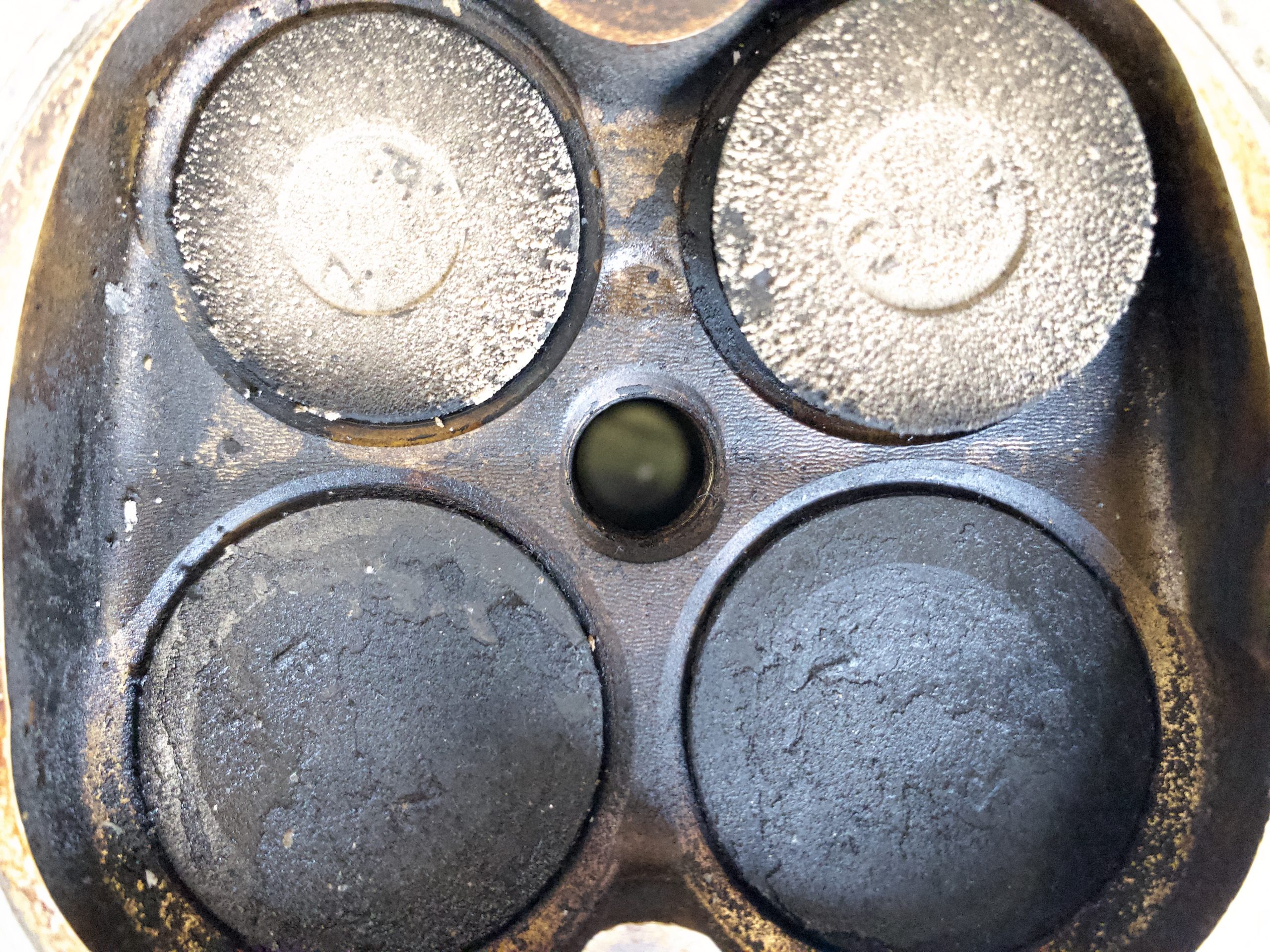
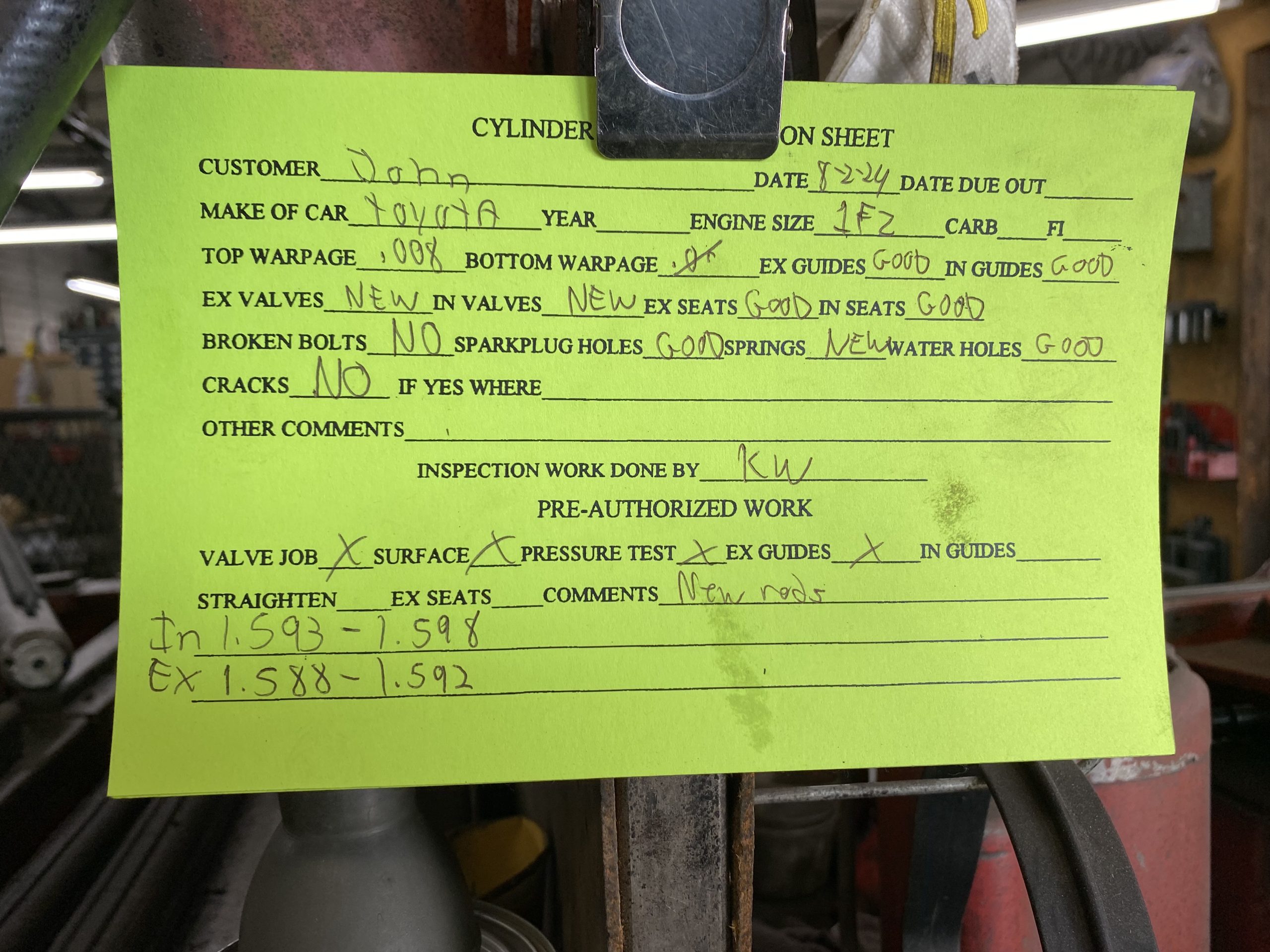
Kyle does a preliminary inspection and measurement of the usual suspects, to get an idea of what we’ll be dealing with as things progress. The one obvious uh-oh is the head gasket, which can be an issue on these vehicles at high mileage. This one is out-of-round on multiple cylinders, and worst on 1 and 6.
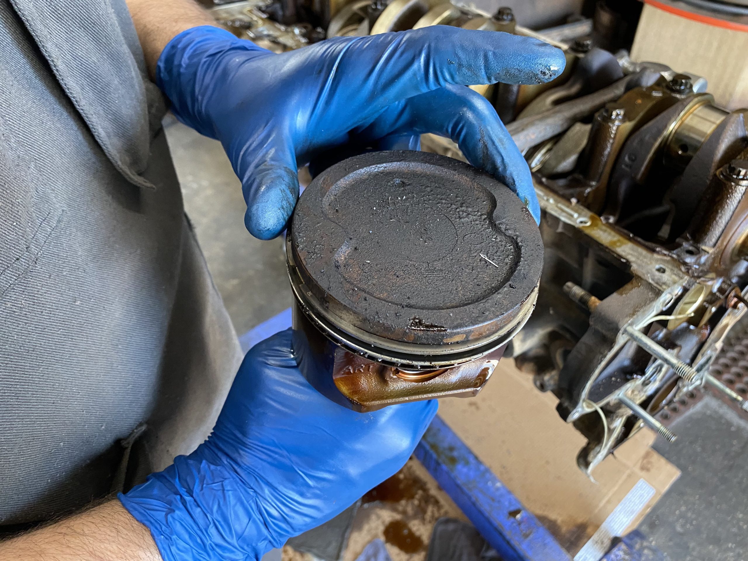
Kyle’s guess is it was already leaking, though not enough to cause serious problems. (Note the pistons lack the “steam-cleaned” appearance typical with bad leaks.) Had we dropped the engine in as-is, we’d have been pulling the head before too long. And pulling the head on a 1FZ, while still in the vehicle, is almost as much fun as pulling the engine. So we dodged a bullet on that one.
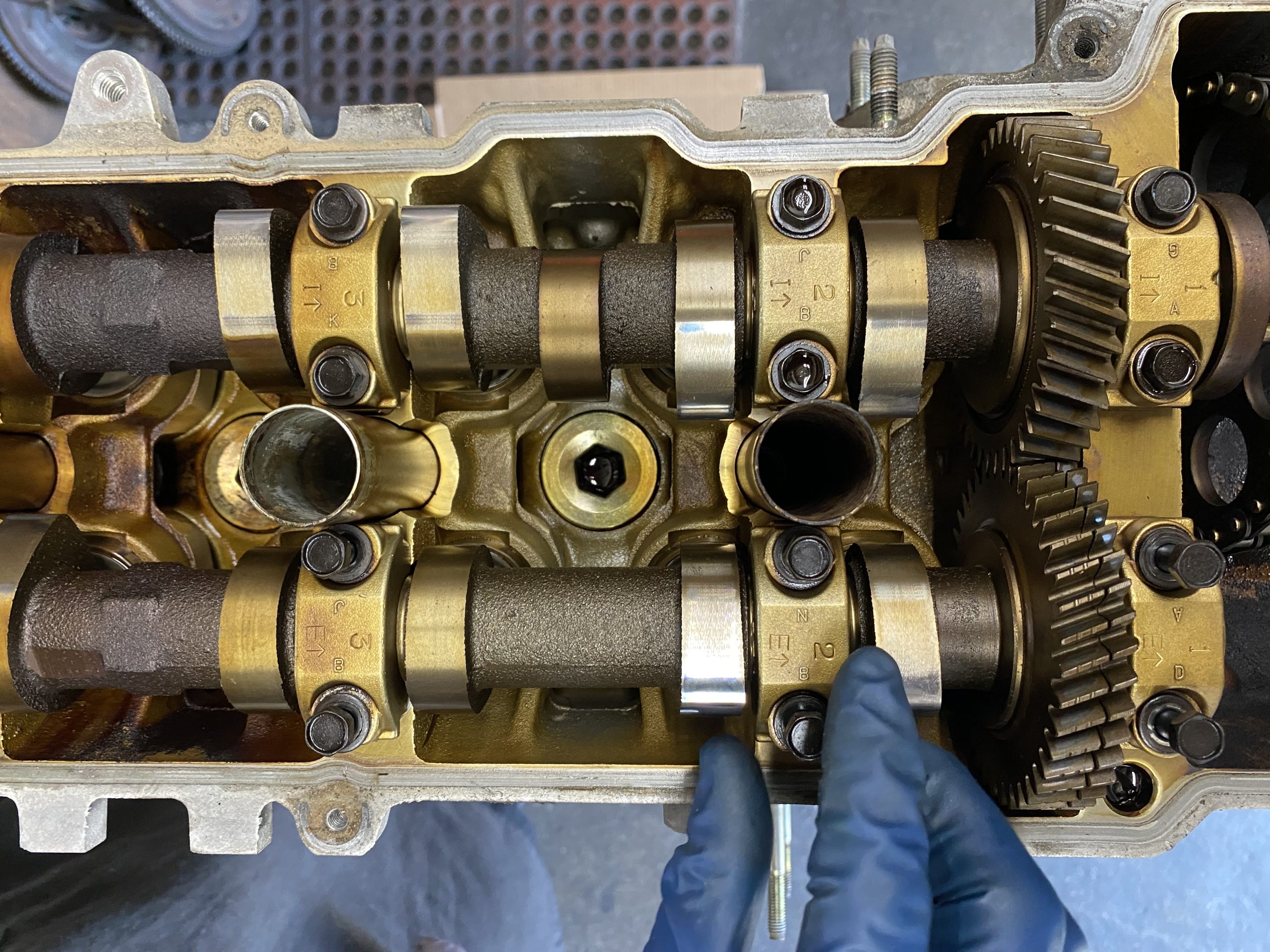
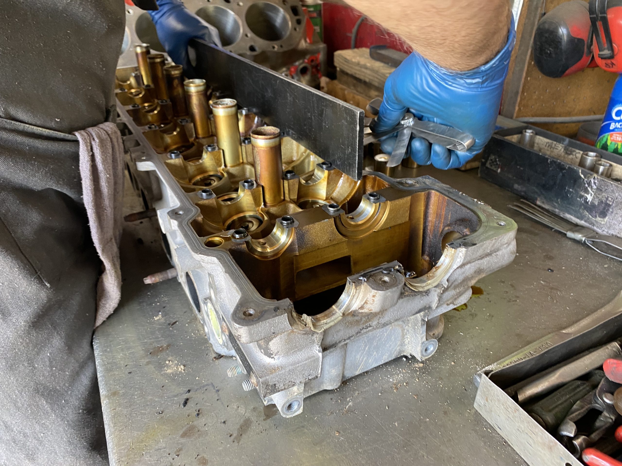
The cams themselves look good, and the top of the head appears clean and well-oiled.
The aluminum head is checked for straightness (no warpage at the bottom, 0.008″ warp on the top).
Roughly 20 to 25 percent of the 1FZ heads Kyle sees are cracked. Fortunately, our head is one of the other 75 to 80 percent. When these heads crack, it’s typically along the valve cover rail, about halfway between the front and the rear of the head, around the coolant plugs in the center of the head, or around the head bolt holes.
Rail cracks can be repaired with TIG welds, but there’s no guarantee the same head won’t then crack in a new location. When cracks are found, Kyle recommends getting a new head, just to be safe. Cracking can be caused by severely overheating the engine. Warping can be due to overheating, or just the repeated expansion and contraction—over decades—of the aluminum head, which is mated to an iron block that expands and contracts at a different rate. (Overheating makes this worse.)
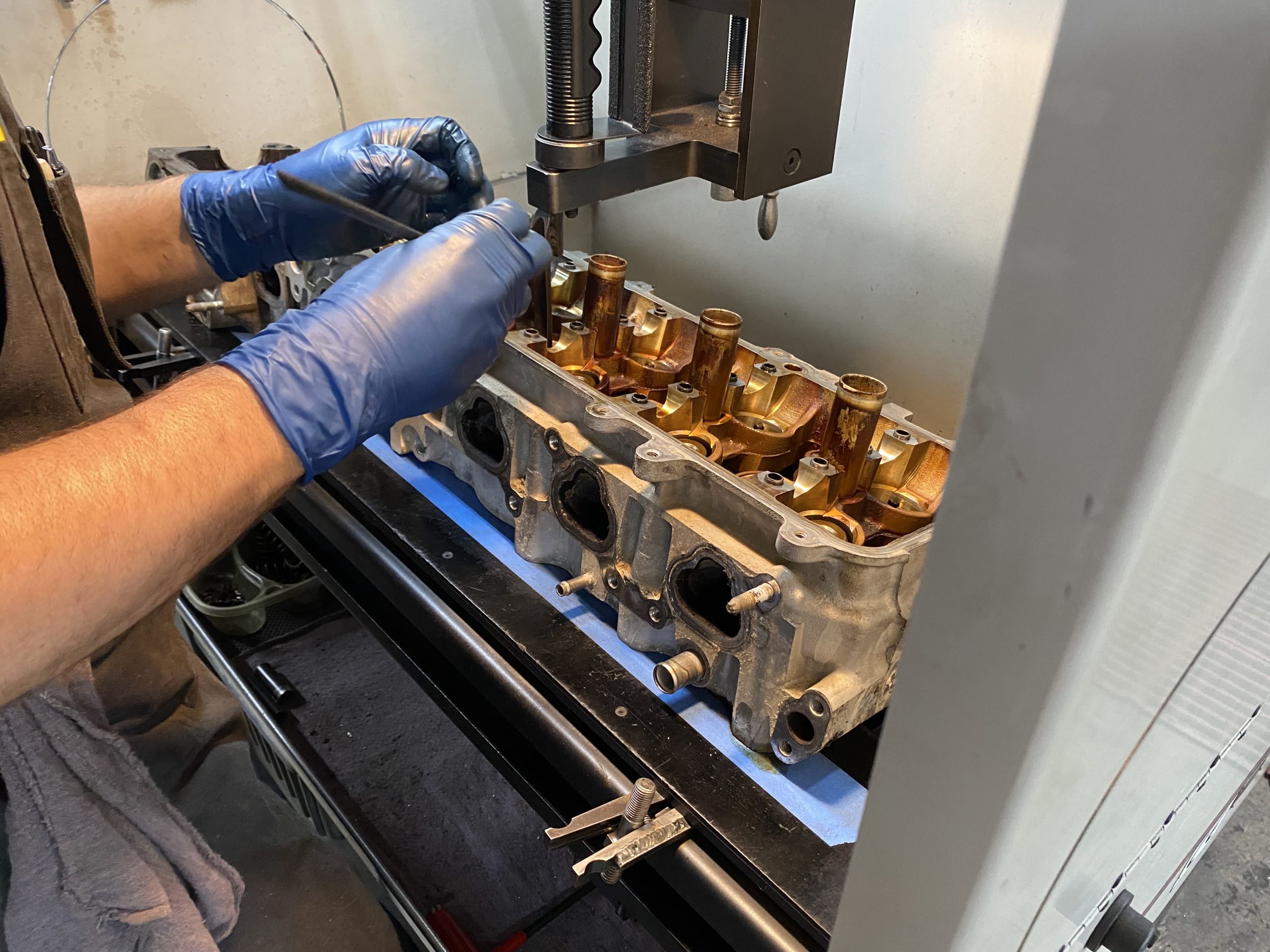
We’ll check the deck later, and Magnaflux the block. The factory steel freeze plugs look good and some folks leave them in place, but we’re thinking to swap them out for brass. (More on this later.)
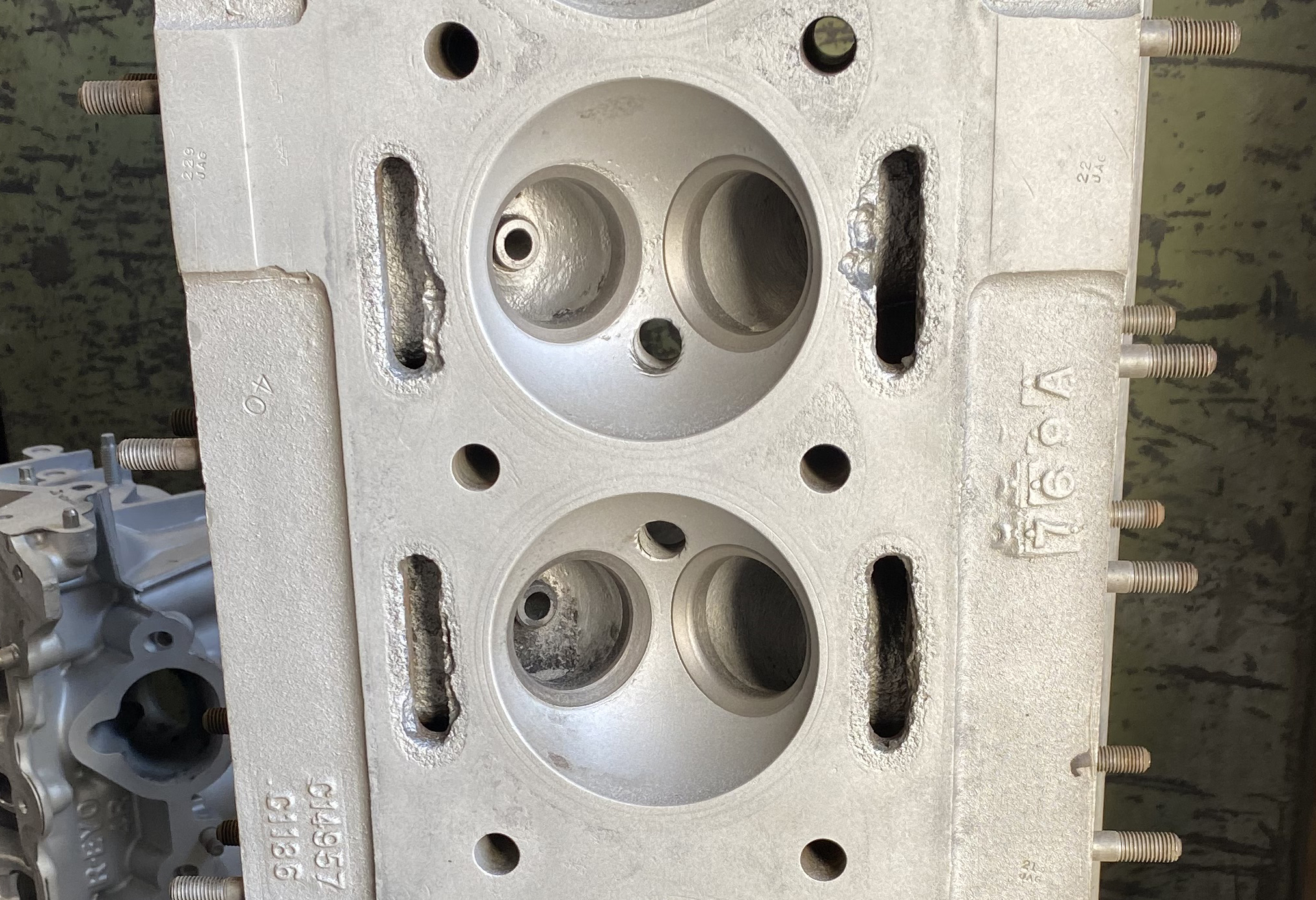
Kyle also checks the visible water passages on the head, as these can corrode if the engine is left sitting for long periods of time, or the coolant (which, like some people, becomes acidic with age) is not changed on schedule. This can also be addressed with TIG welding, at least on the mating surfaces. Our head looks fine—unlike this one…
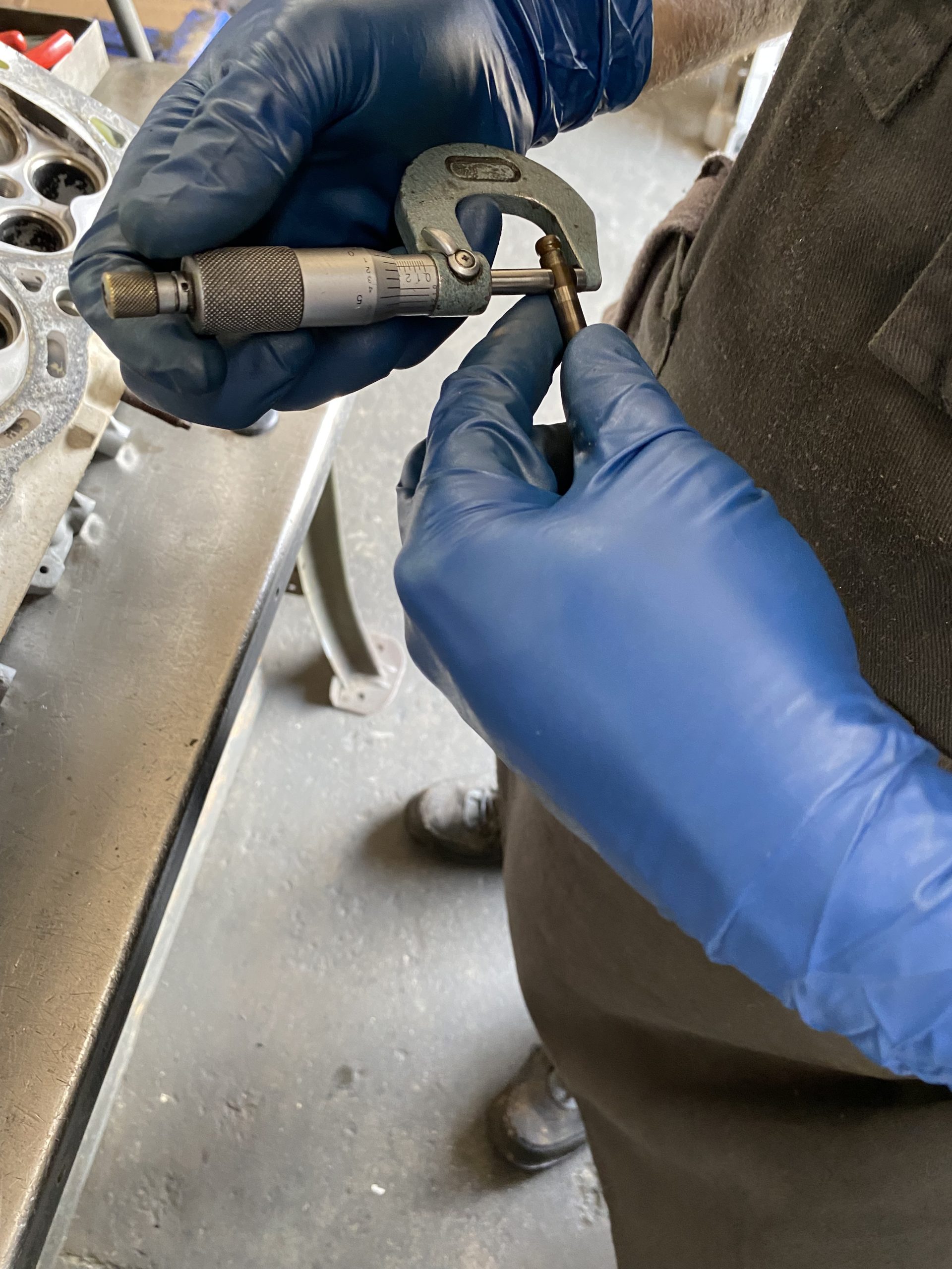
The valve tip height is good, and the valves look normal for the mileage. 1FZ valves don’t typically wear out, but repeated valve jobs eventually make them too thin to regrind. These appear to be the original valves, with no later work done. They should be fine, but we decided to go with new Manley intake valves and exhaust valves. The valve springs are probably still good too (they rarely wear out), but we got new ones (and associated hardware) anyway.
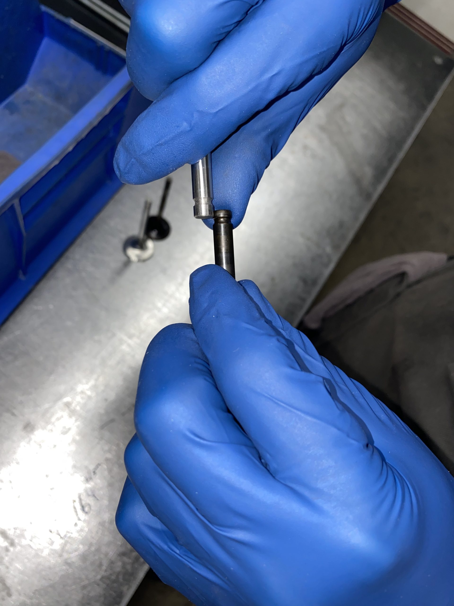
The head is torn down, valve stems measured and compared with the new Manleys. A quick eyeball tells us the working surfaces match up, but the stems are a bit longer than stock. This is because most people use these valves in performance applications, and the stems have to be long enough to reach the small lobes found on performance camshafts. We’re using stock cams, so we’ll have to shorten the stems a bit.
Also for performance reasons, the back sides of the Manley valves have a flatter grind, which allows increased air and fuel flow. This is unlikely to make a noticeable difference on a workhorse engine like this, but we thought we’d mention it.
The valve seats and guides are good. All in all, we seem to have a top-grade head.
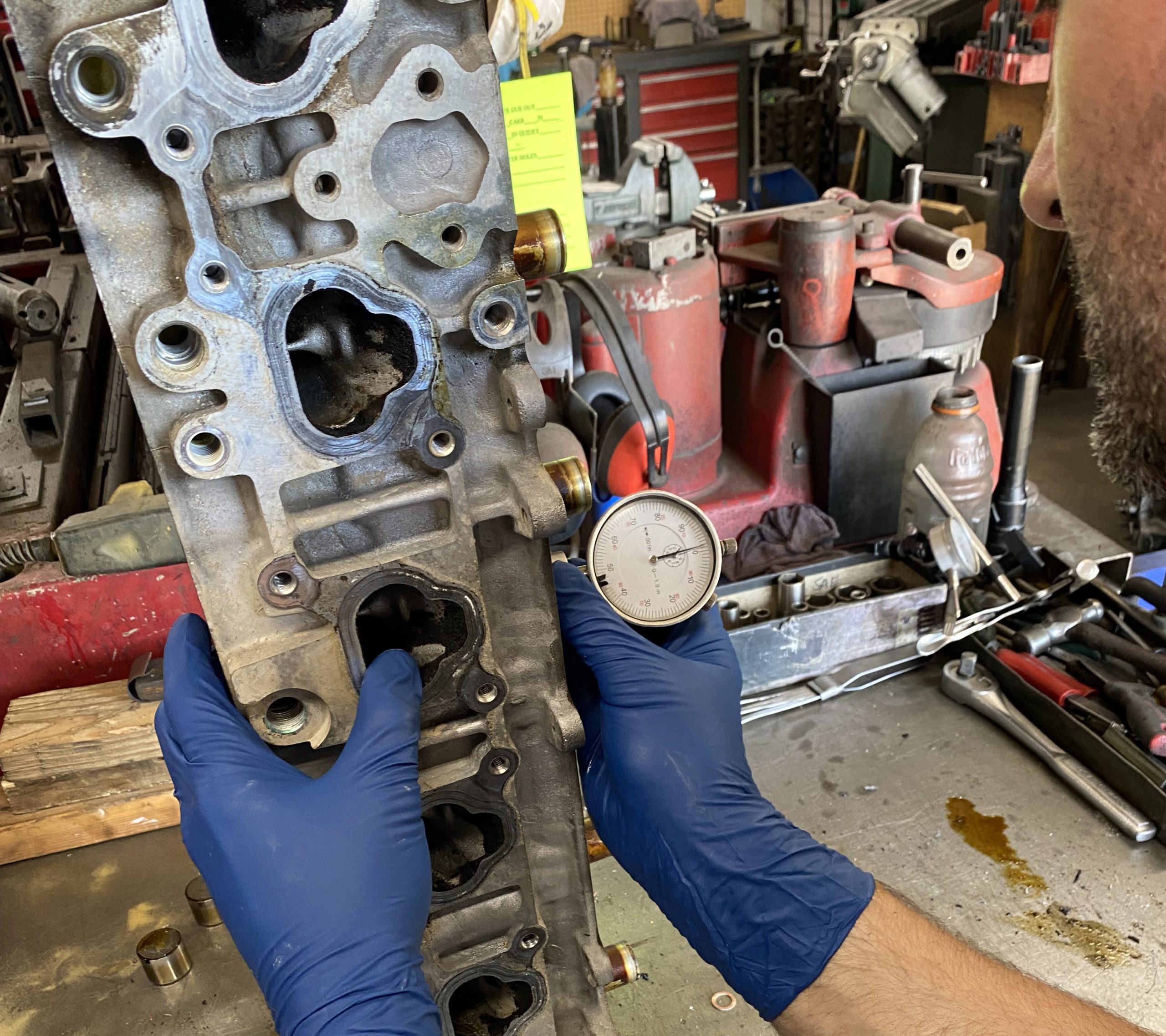
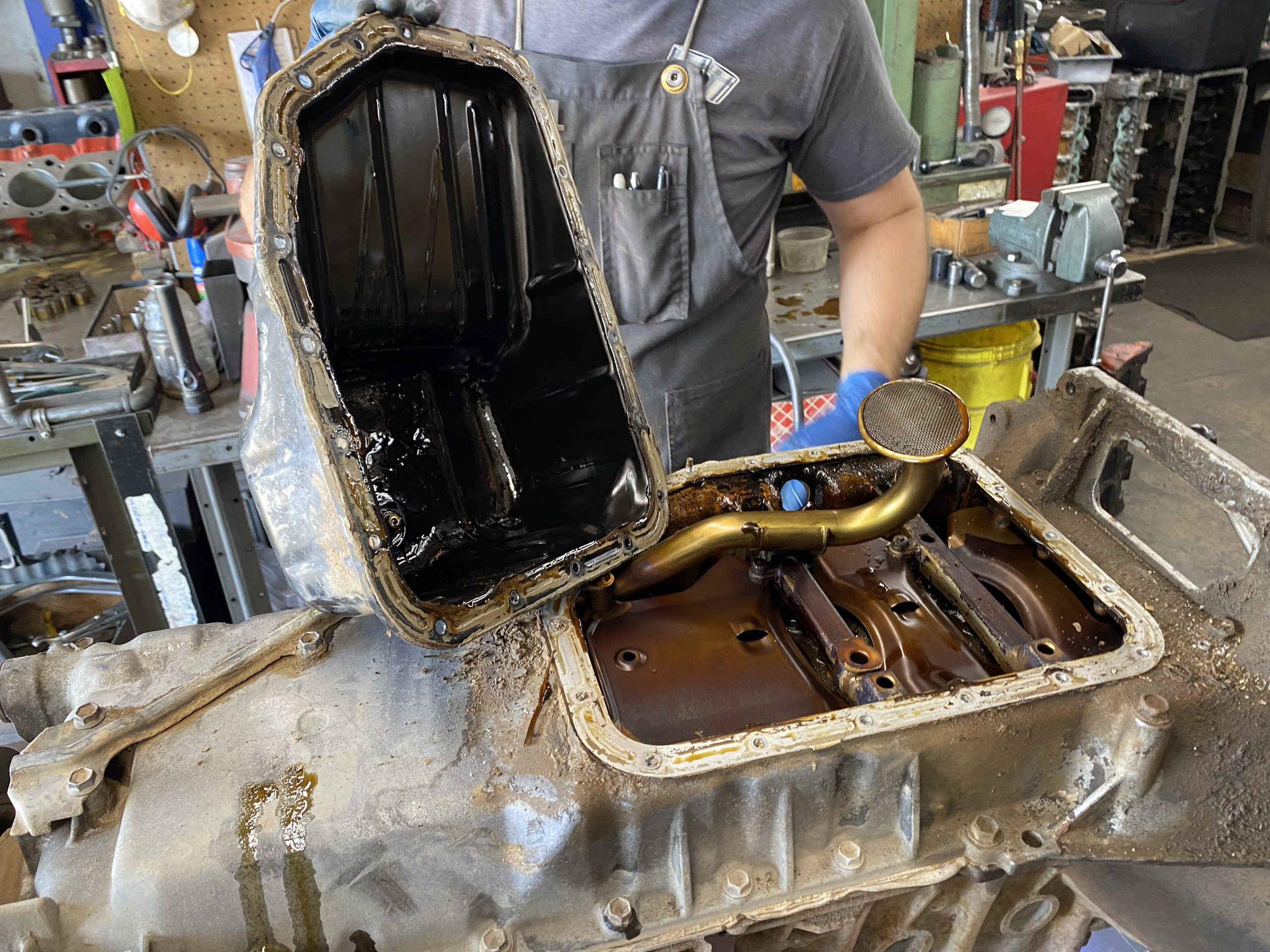
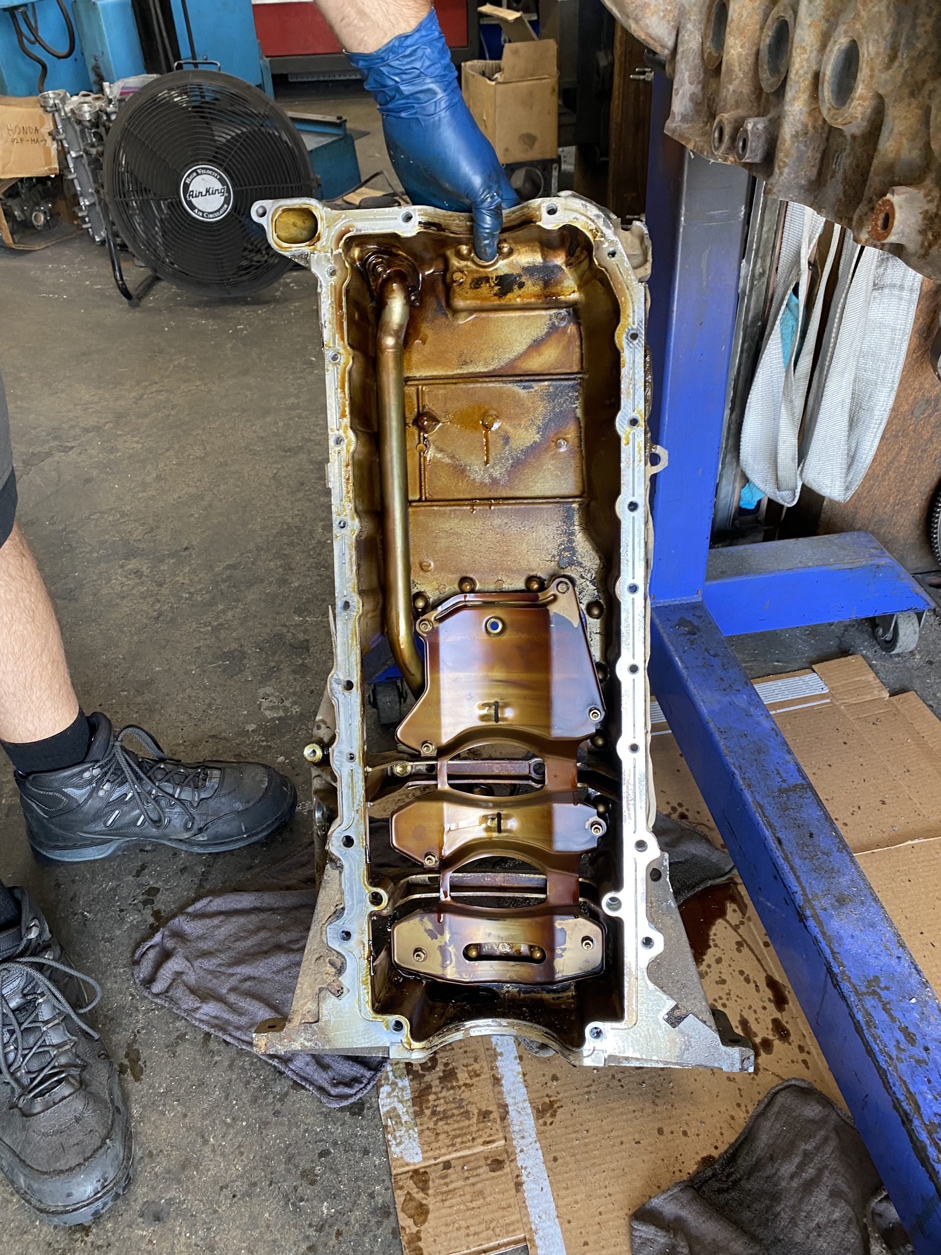
The FZ engine has two oil pans, an upper and a lower (8 quart capacity total). We find the lower is a bit banged up, probably from a rock strike. We’ll have to pound it out or replace it if we want to be able to drain the oil properly down the road.
The upper pan is fine, and both show clean oil. You need to be careful prying on the upper to get it off; if you pry too hard in the wrong place, it can crack in the middle.
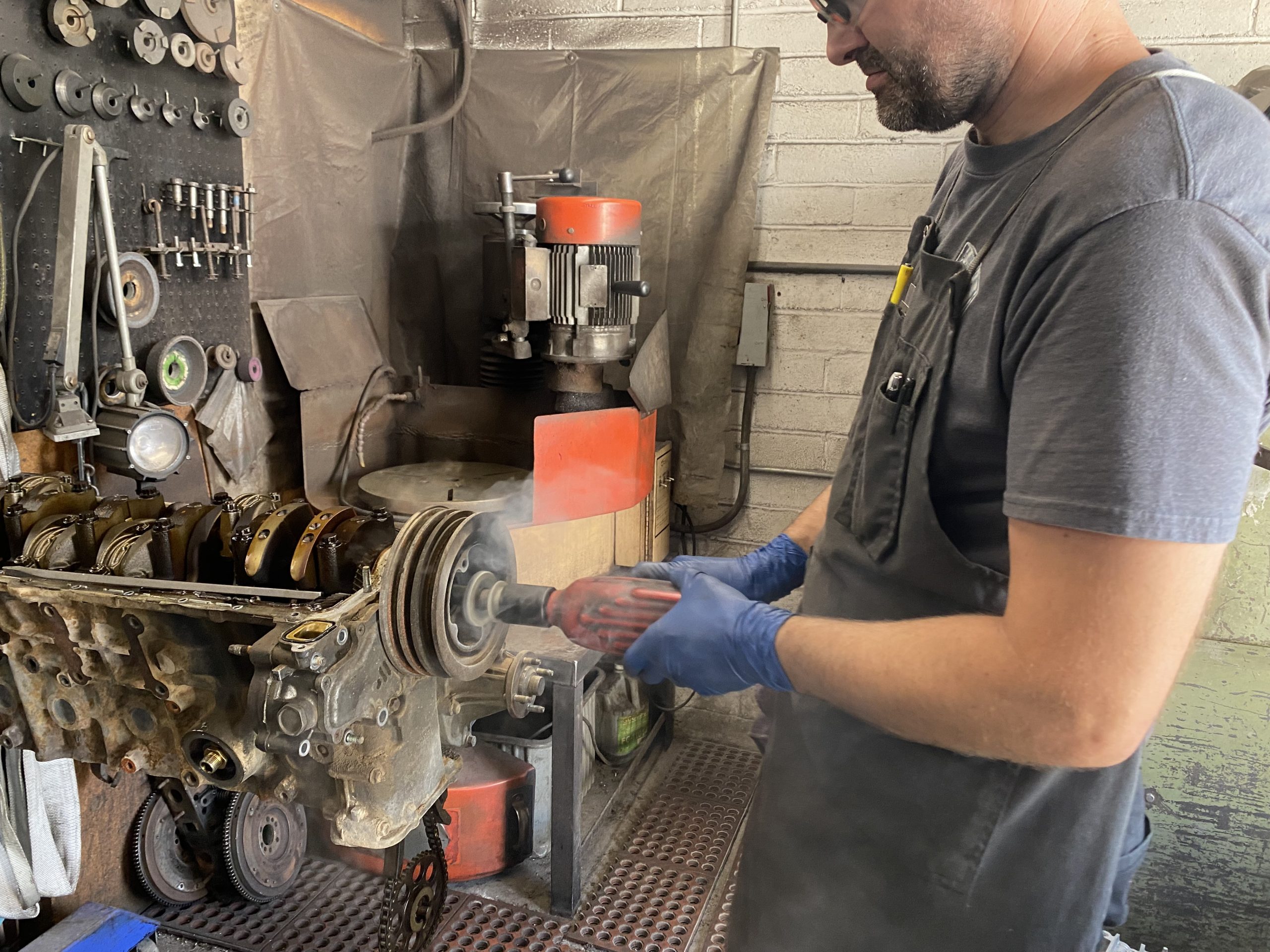
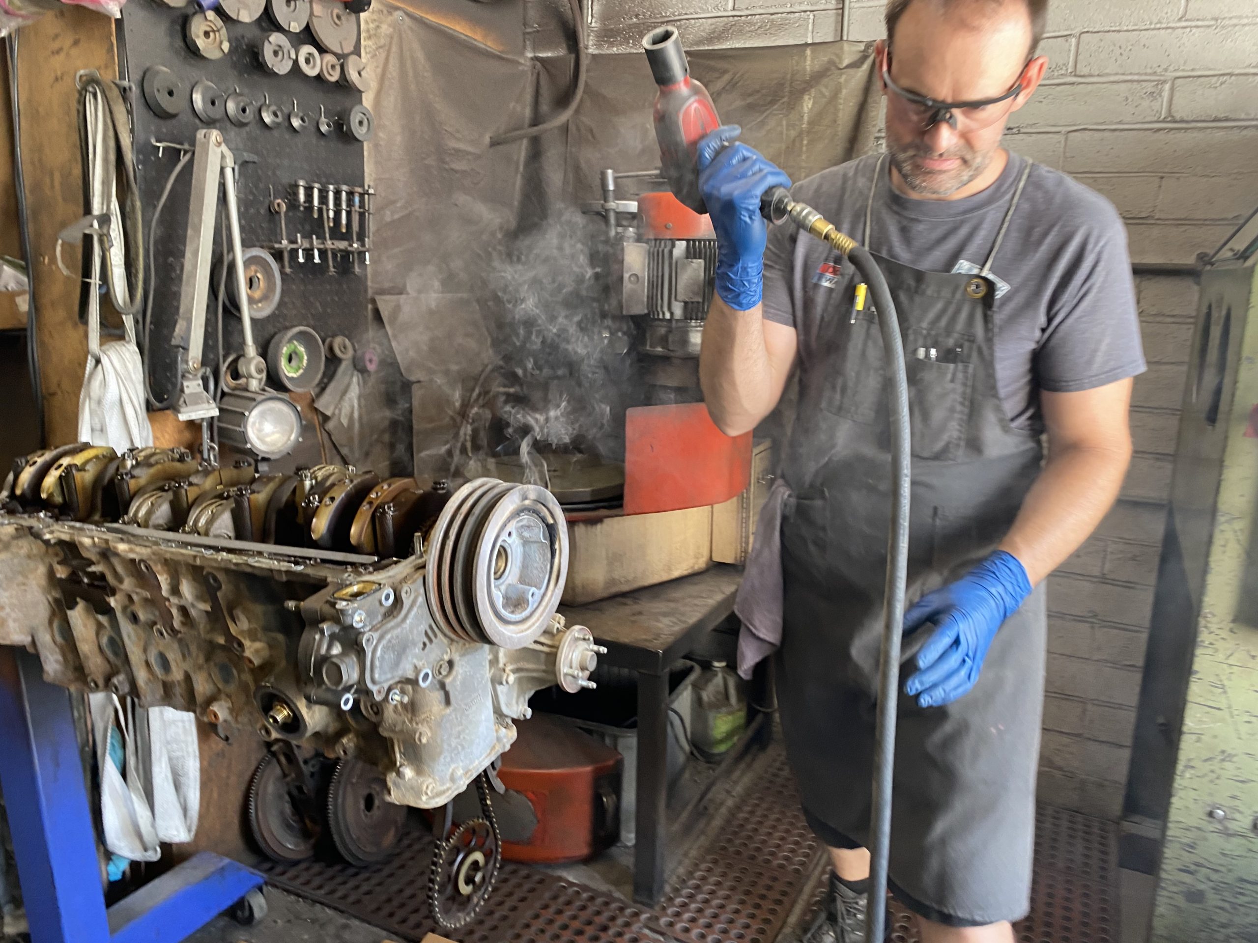
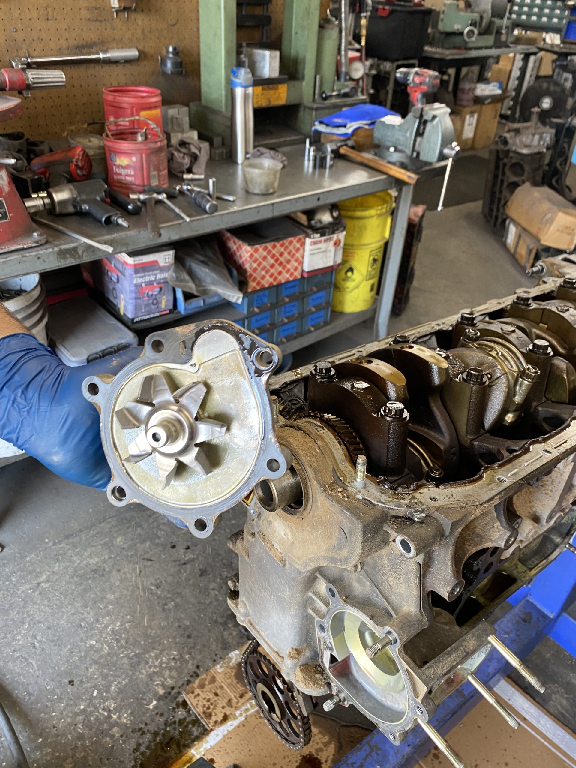
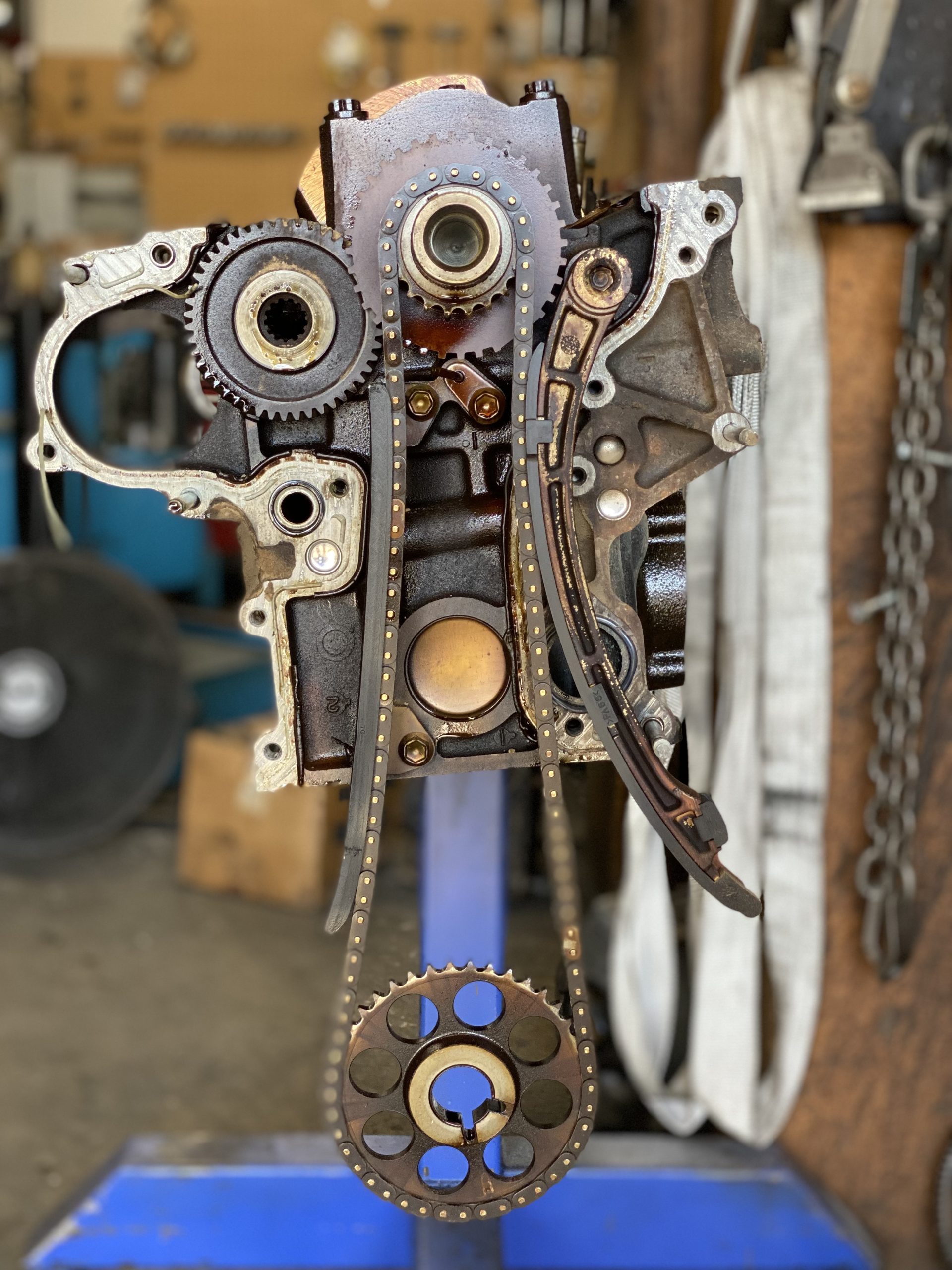
We pull the water pump; clean as a whistle. Then the timing cover, revealing the steampunk timing set. We’ll be replacing the chain, damper, slipper, and tensioner. Also the gears, which are probably fine—but it’s a real pain to pull that cover in the vehicle, so we’ll call this PM.
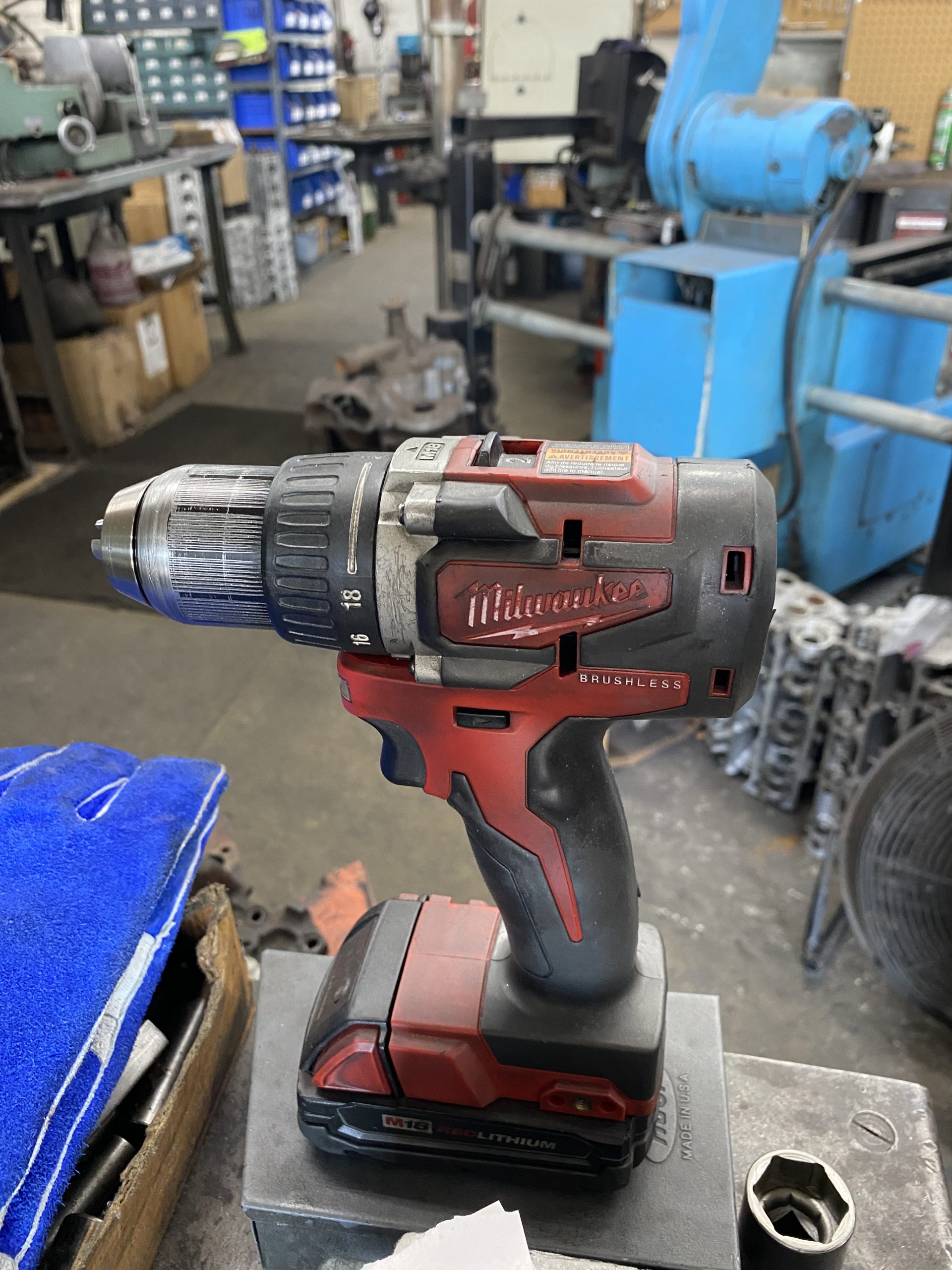
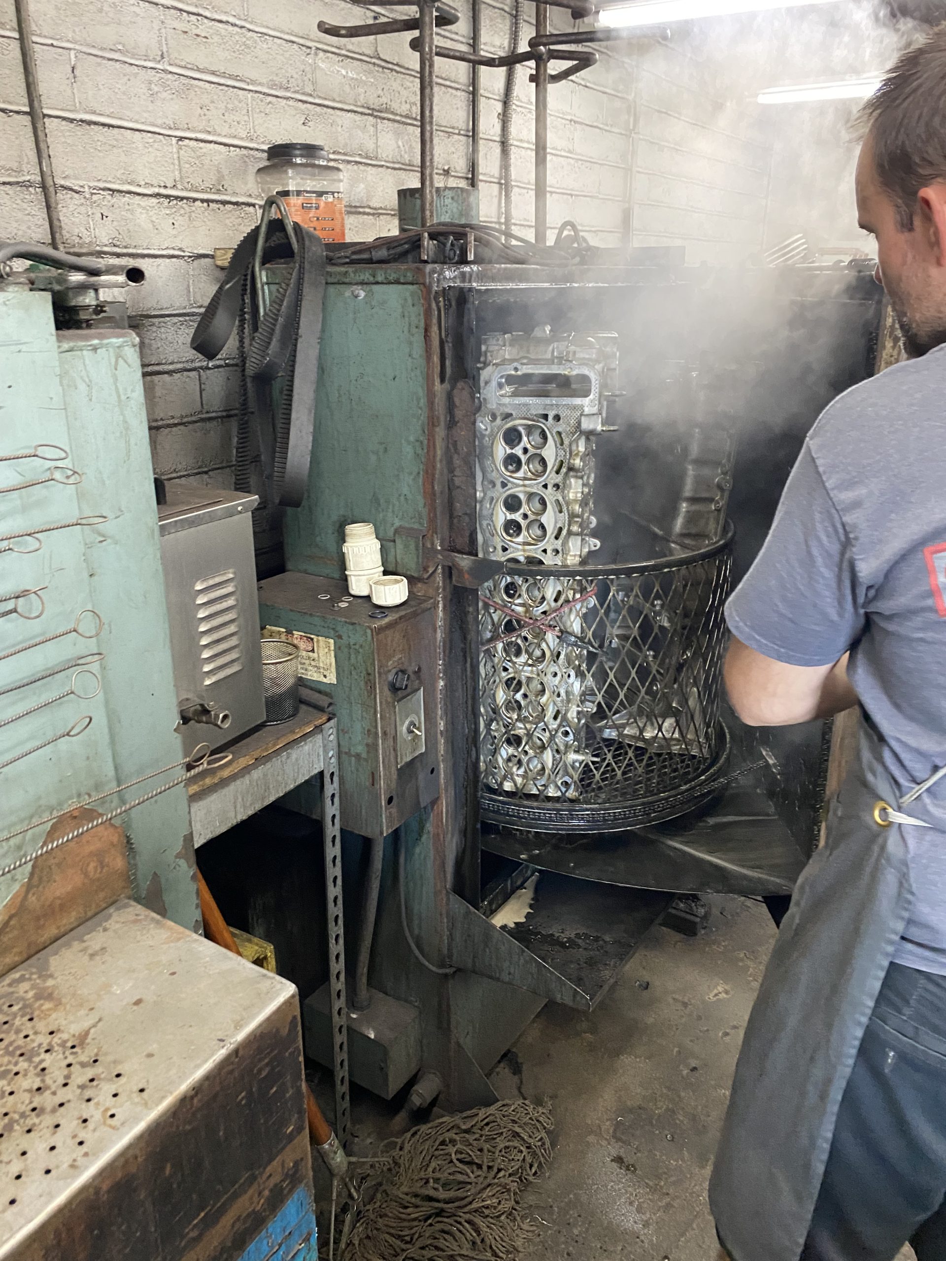
A bunch of parts go in the Jet-Spray. On the way back, we notice that Kyle likes Milwaukee too—though his have a little more mileage on them than ours do…
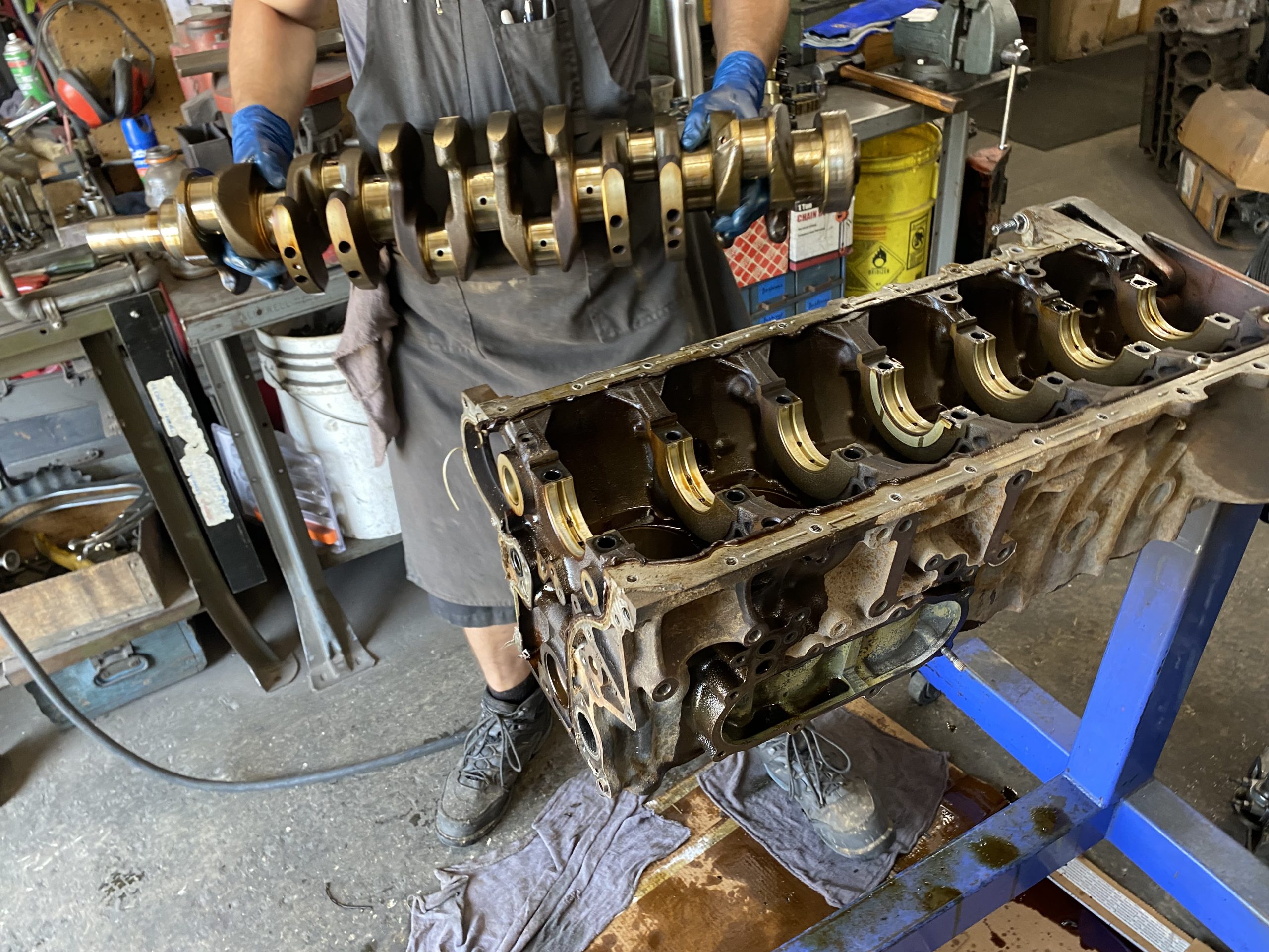
Next we dive into the block. The fluid colors are normal and the engine shows no signs of having been seriously overheated, though the scent of the deepest oil suggests things might have gotten a bit toasty now and again.
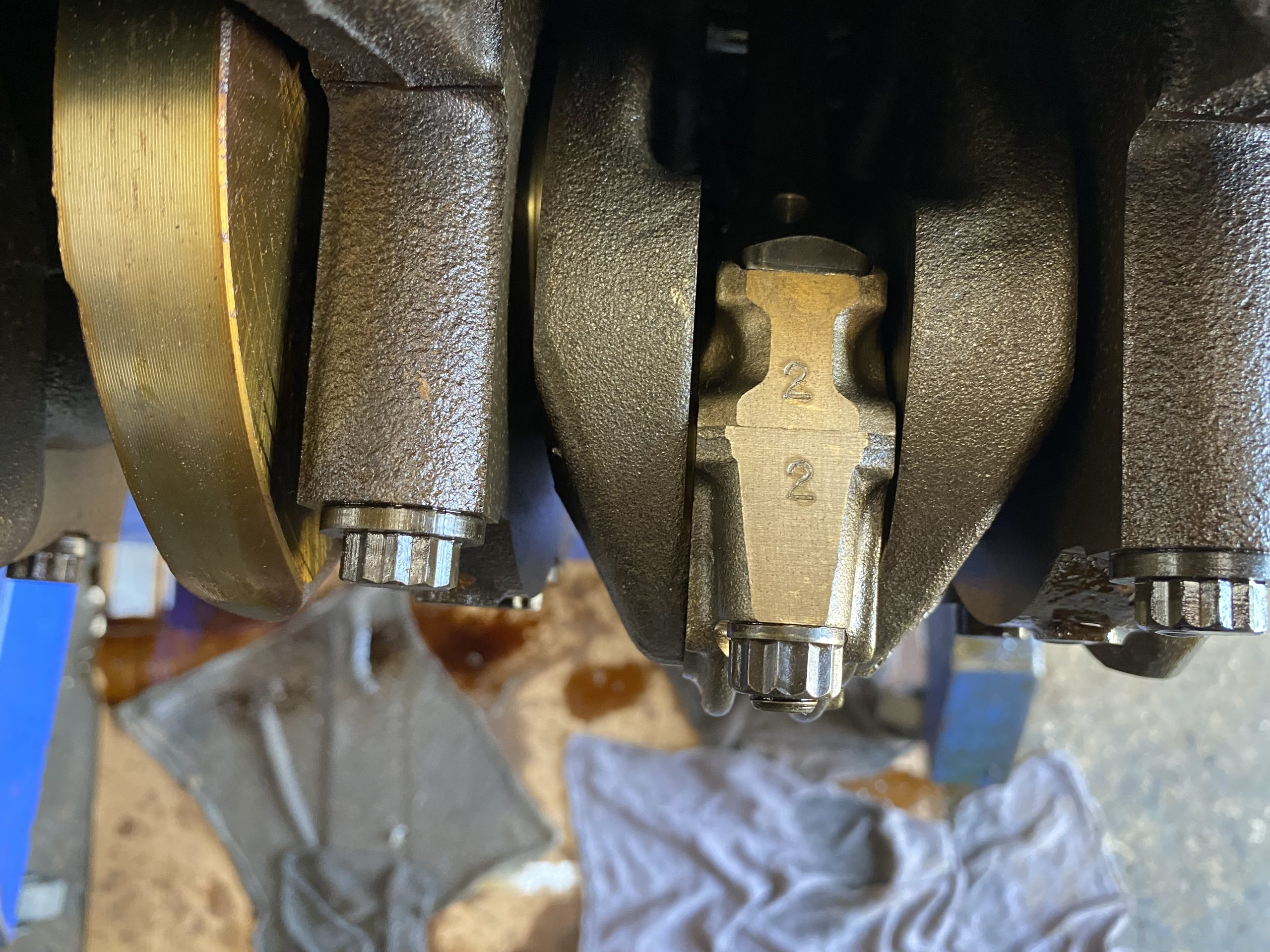
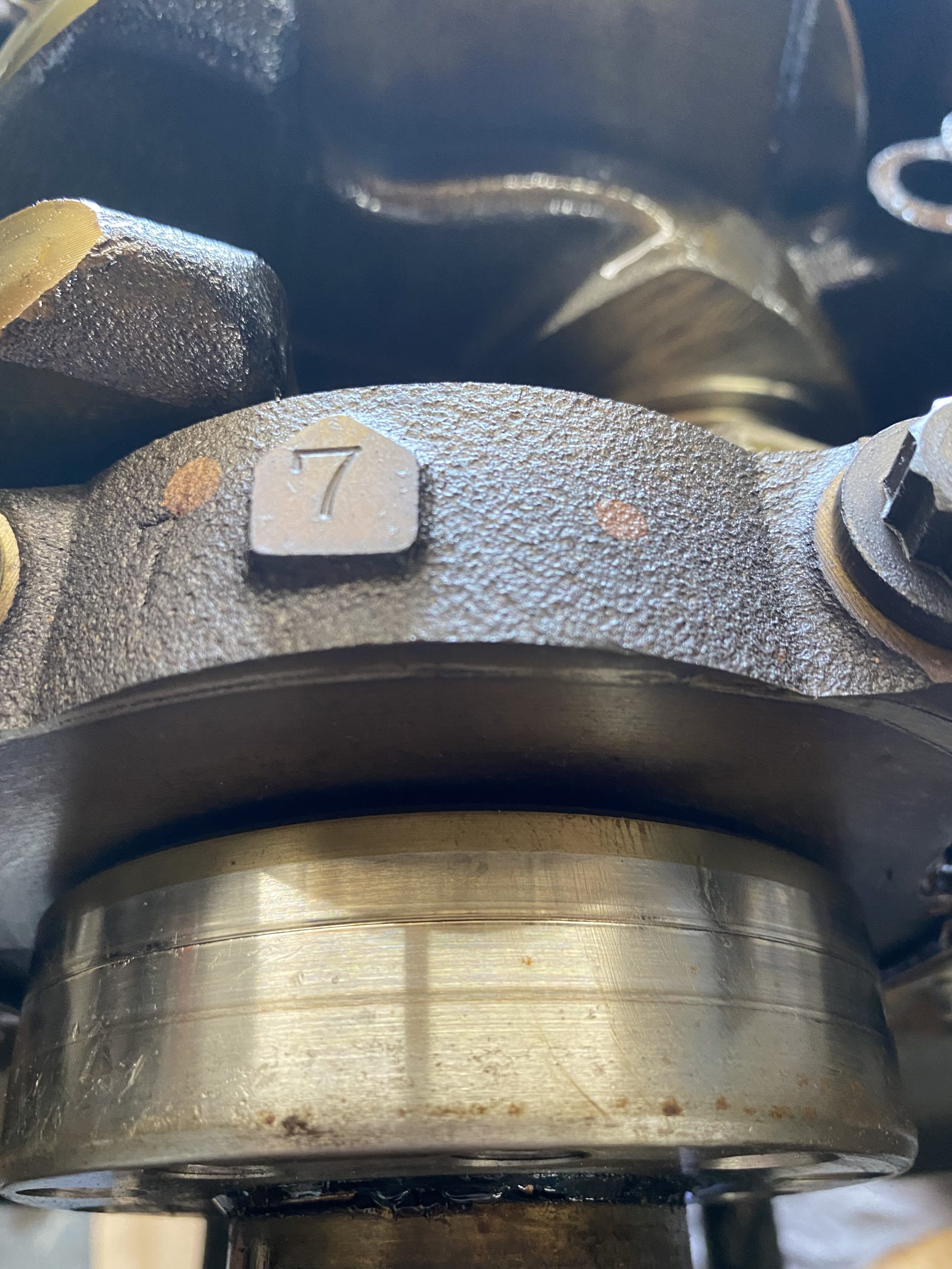
Kyle numbers the rods and caps before disassembly. The fact that no one else did this is a pretty sure sign the engine’s never been apart before. Again, things look darn clean, which indicates our donor motor was well looked-after.
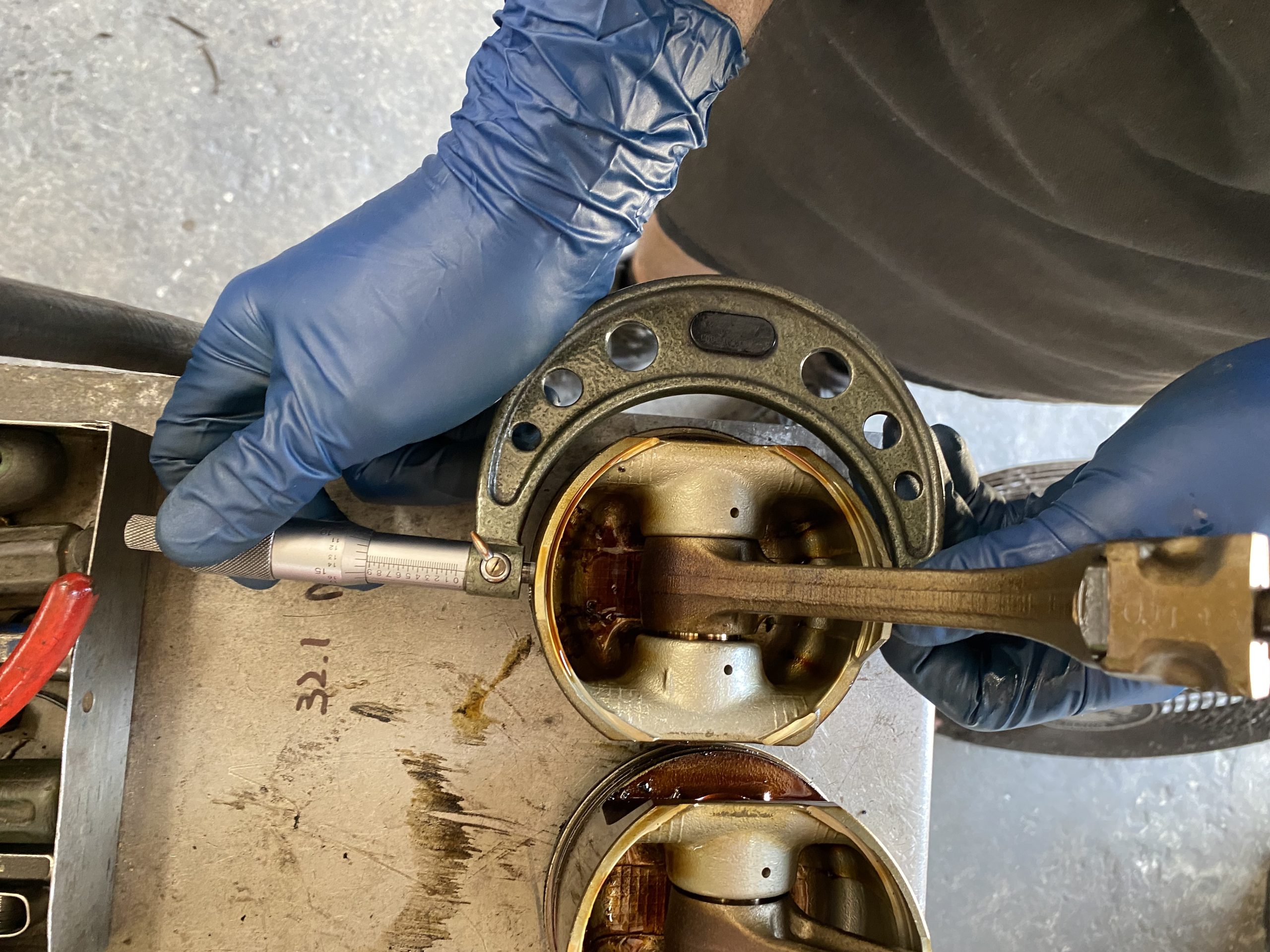
Rod bearings are inspected—normal wear for the mileage—then pistons eyeballed and measured. They look about right for the mileage, and seem to be in reusable shape; we’ll know more on that later.
Hot Tip: Measure your pistons at room temperature, around 68 to 72 degrees. Leaving them in the sun and then measuring them will give you the wrong numbers, because the heat will cause the aluminum to expand.
So far, so good…
There are no Toyota-quality aftermarket cast pistons, and because our goal is long-term reliability as opposed to top-end performance, we’re giving forged pistons (no matter how good) a miss. Still, with five different piston options from Mr. T, there are choices to made. More on this in a future installment, when we measure the bores and make those choices.
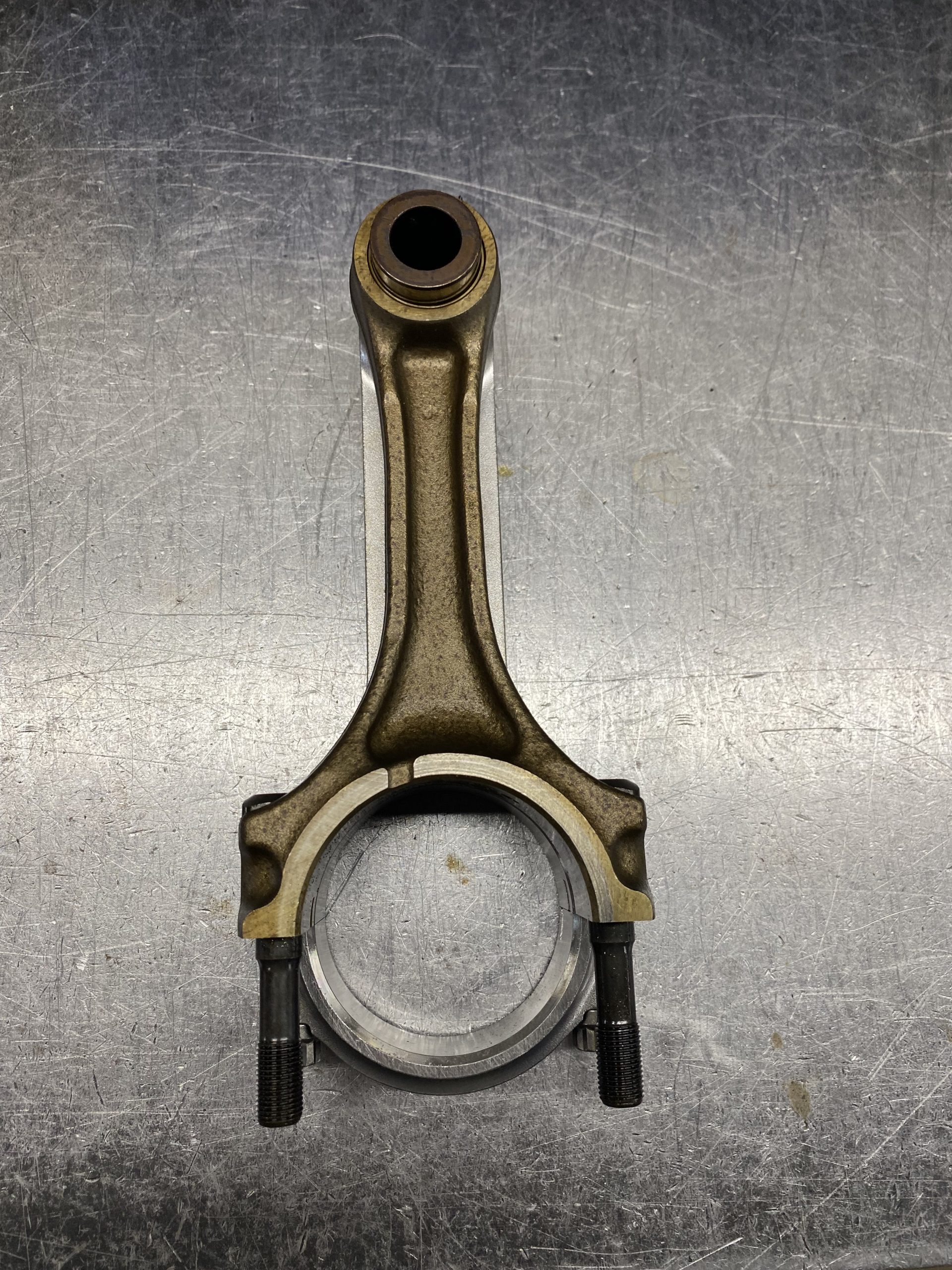
Though there’s not much to go wrong with piston rods, we decided to go with new Manley forged H-beam rods because, why not. They’re considerably beefier than the stock rods, and the wrist pin and bearing surface measurements are a dead-on match for the originals (which isn’t always the case with aftermarket rods).
As a bonus, the Manley rods come with ARP hardware. If nothing else, these will make us feel better if we ever find and fit a supercharger. (Toyota did offer one, briefly, but they’re now rare, and often have missing/worn parts when you do find them.)
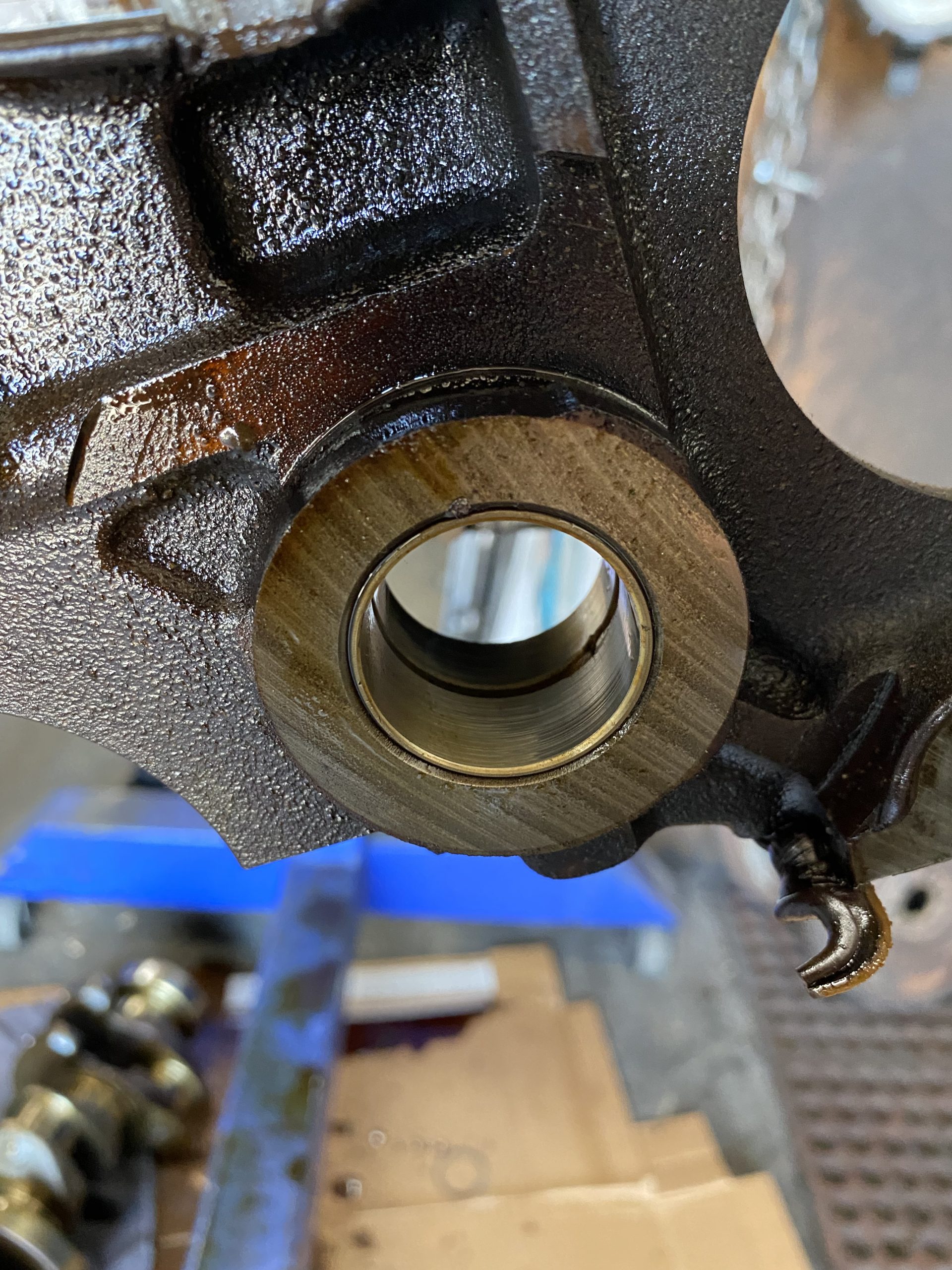
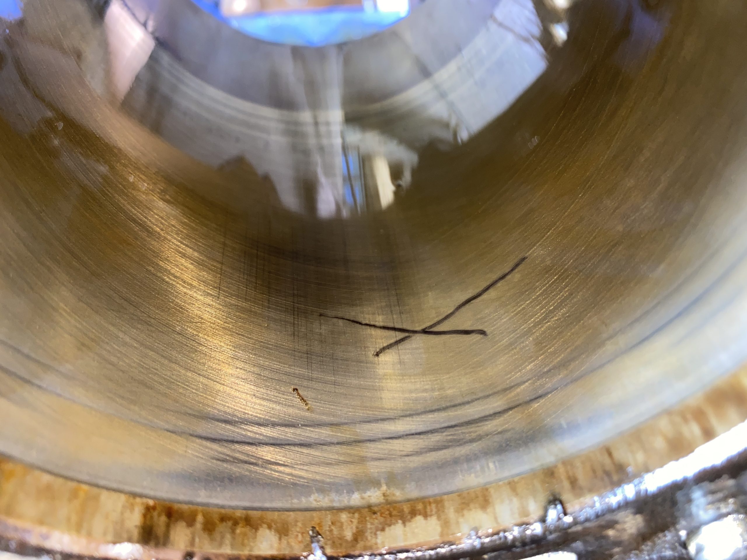
Next we take a look at the surface where the rear main seal seats on the crank, and see the little groove worn-in over the past three decades. There’s one like this on the front, too. We’ll dodge these grooves later.
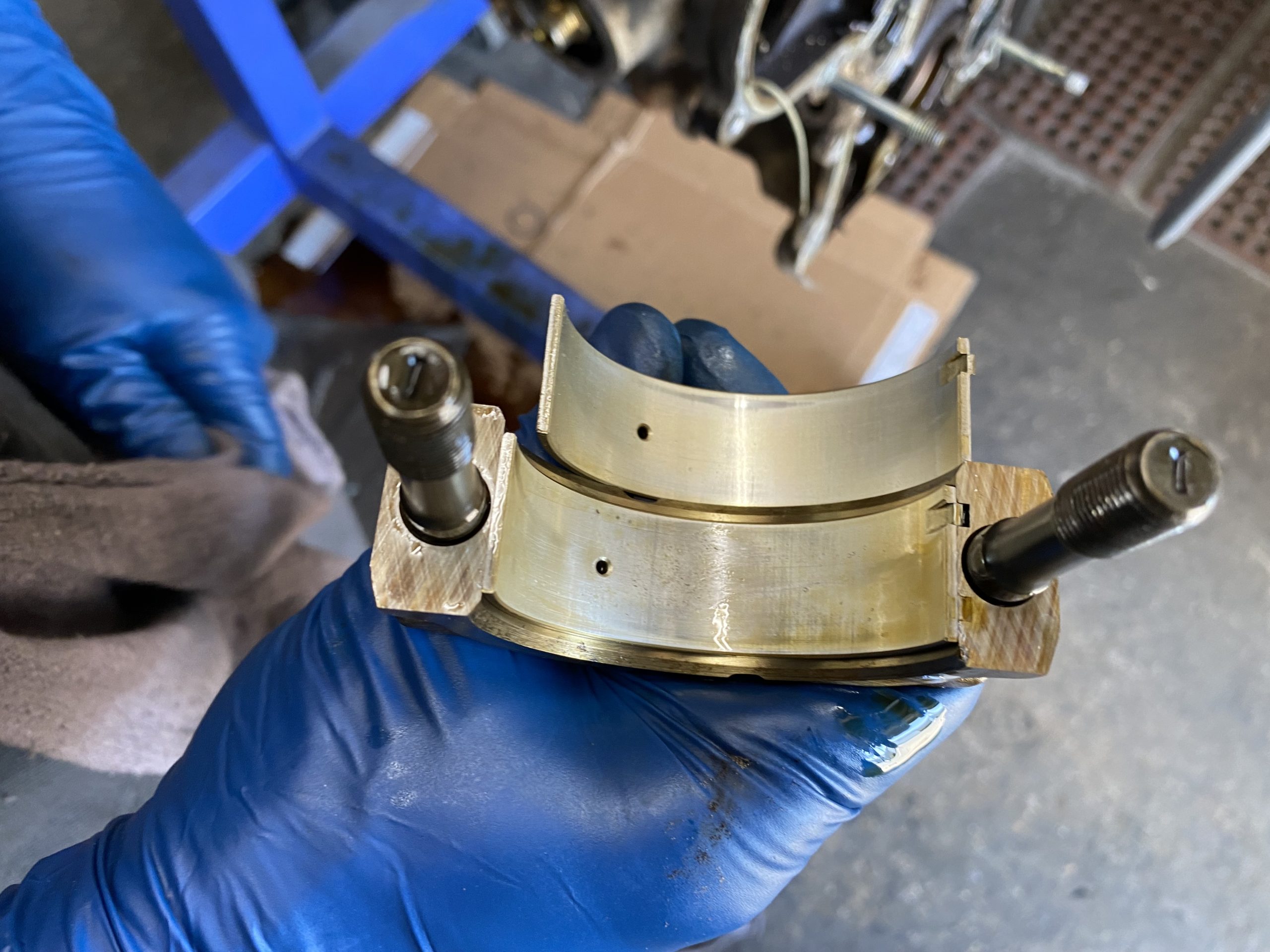
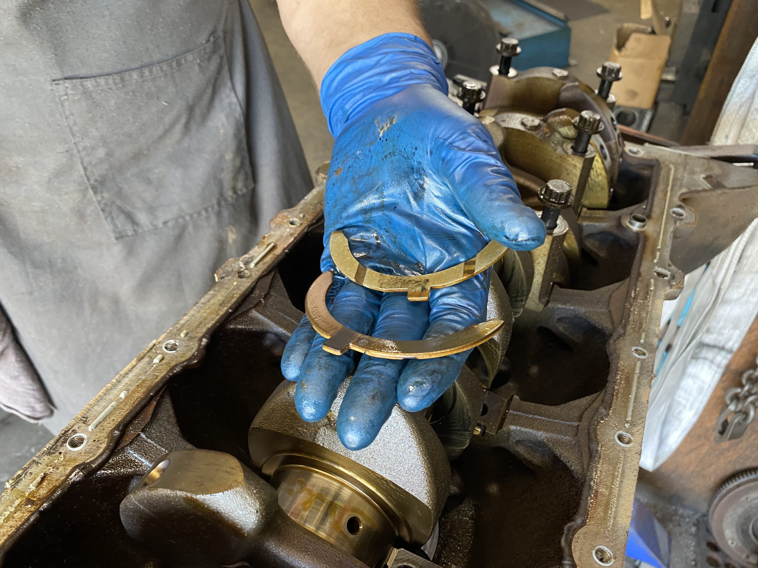
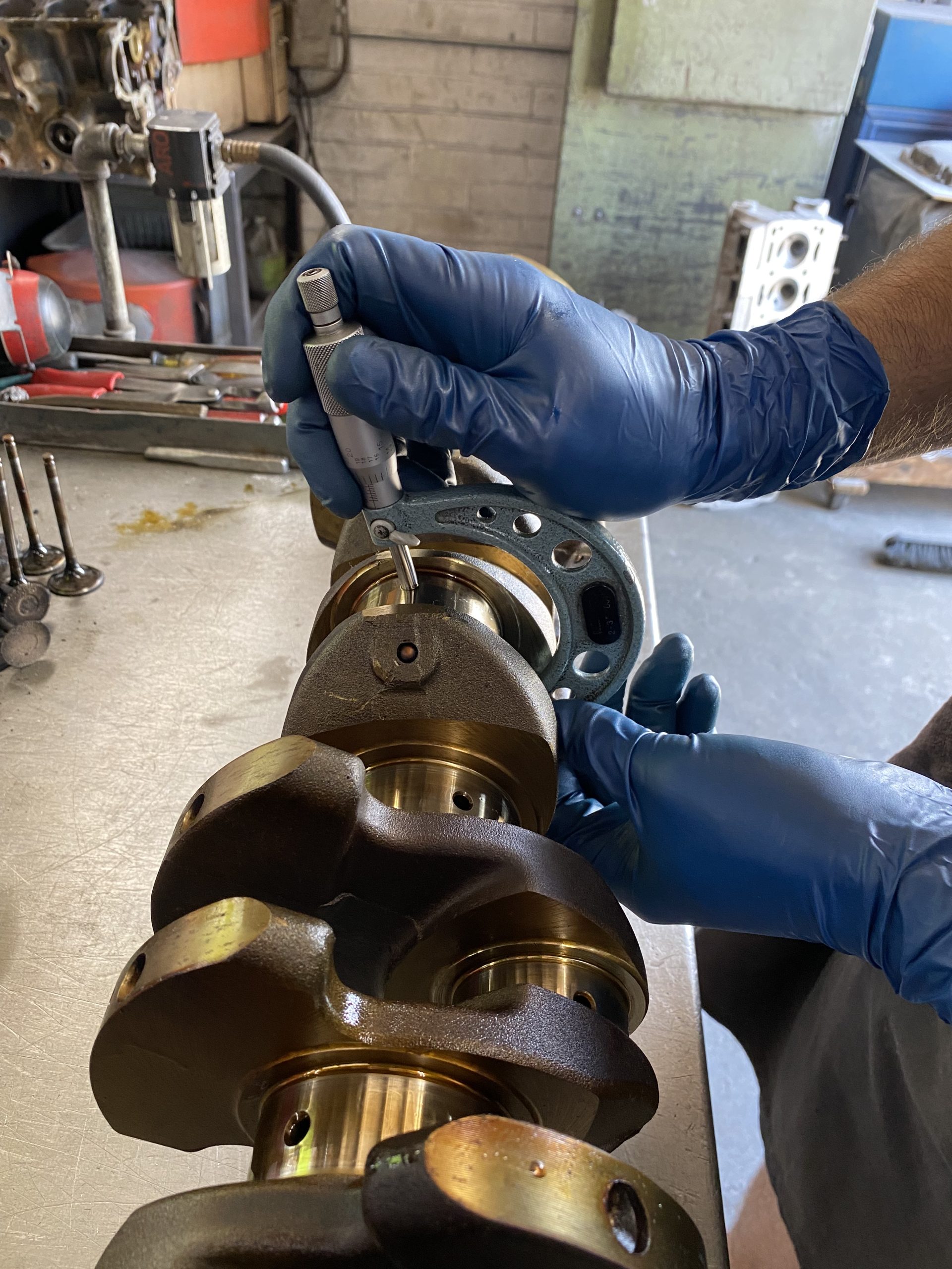
The thrust washers come out, repeat after us: normal wear. The mains come off, and Kyle pumps iron with the crank, then measures the journals—which are dead-center on the spec range.
Main bearings: normal wear.
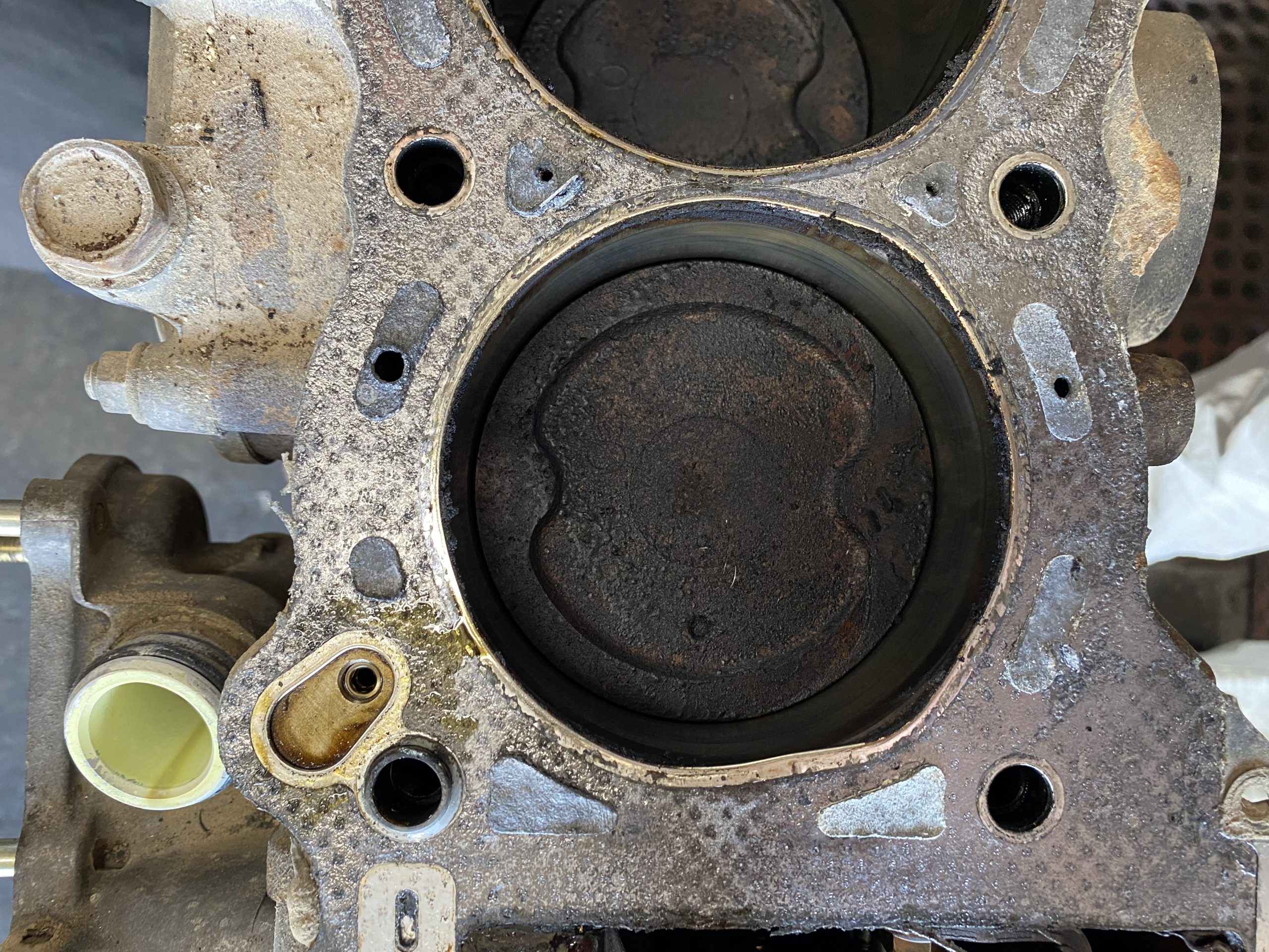
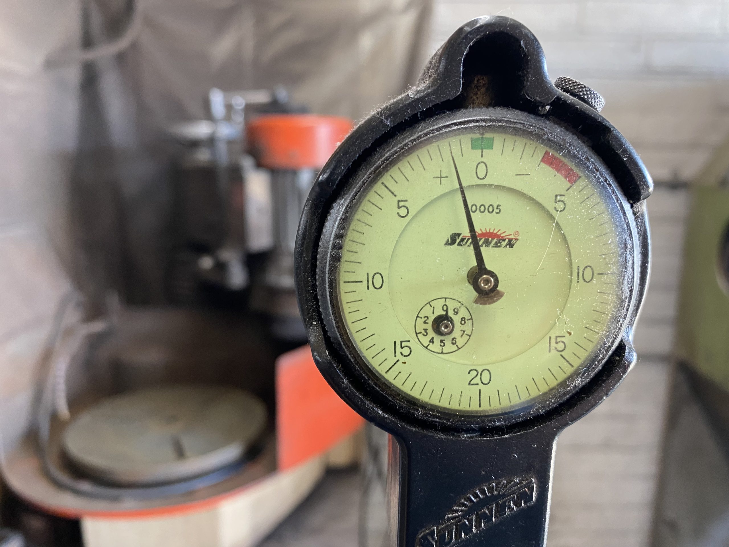
Peering down the bores, we can still see the factory crosshatching. The bores are still round at the bottom, and only 0.0015″ wider at the top. Looks like we’ll be honing instead of overboring.
After that, we’ll check again in 250,000 miles—or our future kids will.
round (Image/J Robert Marlow)
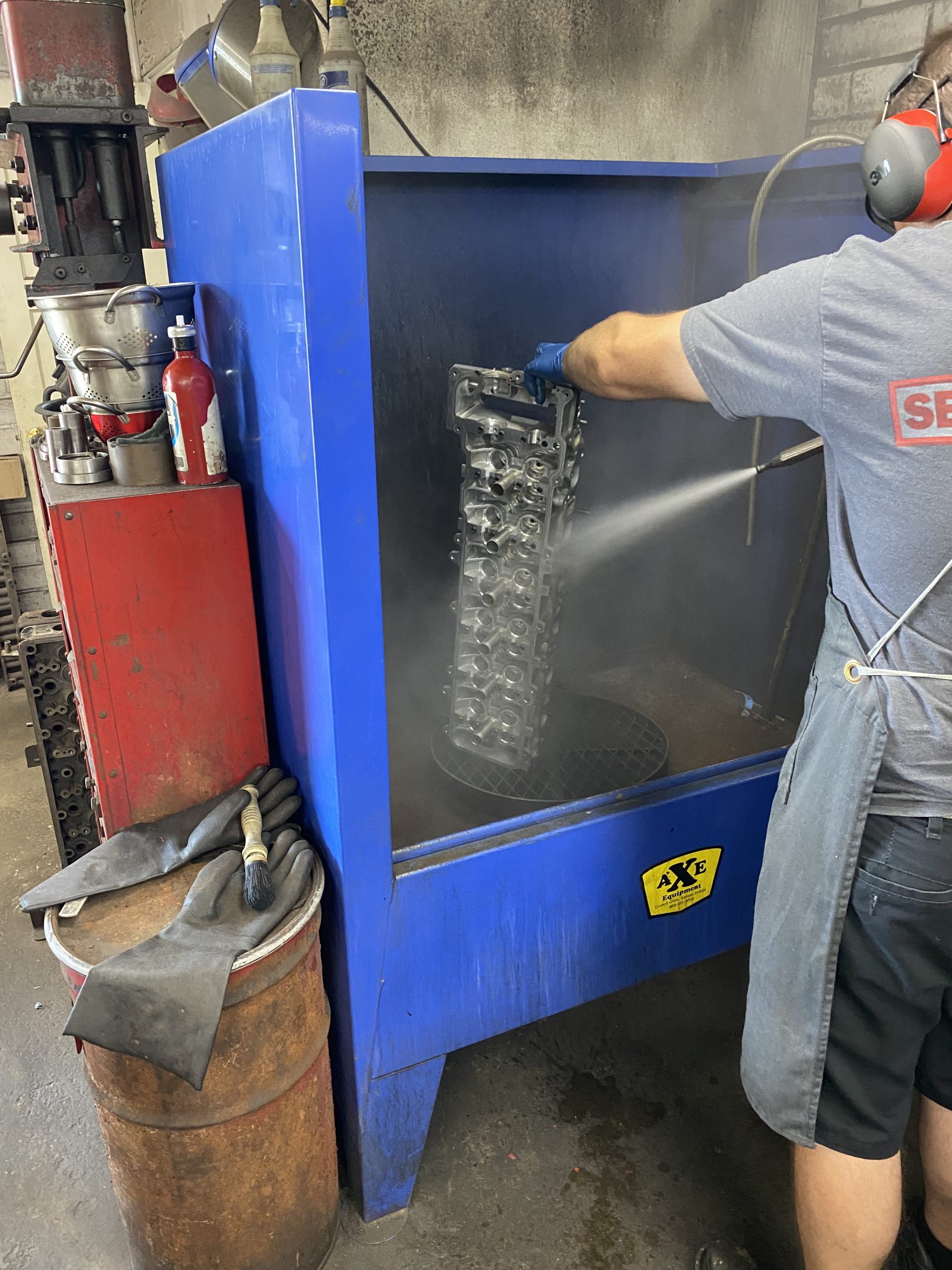
The first parts come out of the Jet-Spray for power-rinse and drying. They look almost new already, but Kyle’s not happy, so they’ll be washed again later.
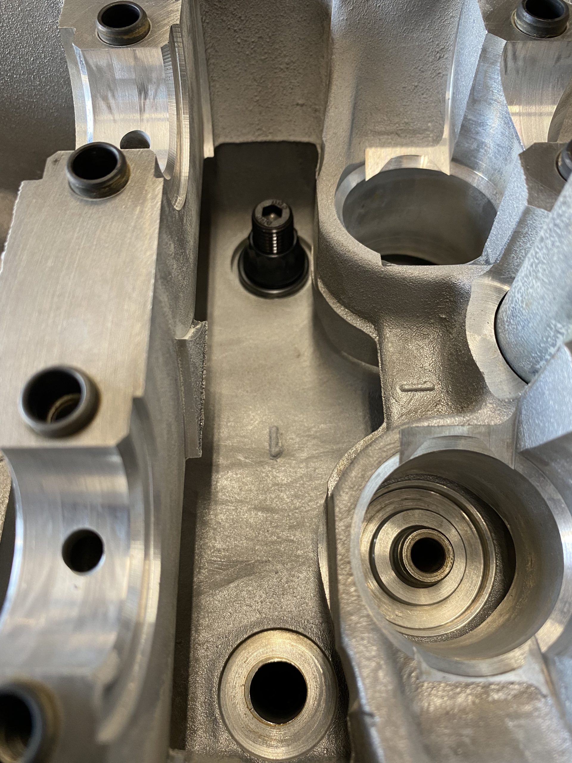
The last thing we do (for now) is test-fit our new ARP head studs. None of the stock ARP options are a perfect fit for the FZ engine (though Supra studs can be made to work if you don’t thread them all the way into the block.) So we talked somebody at ARP into a custom set, with the idea they might want to offer that for sale—still trying to talk them into the sale part.
The challenge is this: there’s plenty of room for protruding studs under the cams—but, the cam gears reduce clearance on the front two studs, which can’t poke their heads up much beyond the nut. Our first try at custom studs has only 0.02″ clearance at the cam gears, which is a little too close for comfort. The good news is, we have 0.380″ of stud above the nut, so we can shave off quite a bit.

Why switch to studs?
Well, they’re stronger and less costly than the OEM bolts, so what’s not to like? That said, we don’t need that extra strength on an engine like this, but we like knowing it’s there. Using studs also makes it a heck of a lot easier to pull the head without pulling the engine to do it.
Not that we expect to—but what if we have to? As you’ll recall, the first major-hassle thing to go on these engines is the head gasket. Even if that’s 250,000 miles down the road, we’ll sleep better knowing the job will be easier when we’re ninety. (And don’t think we’re kidding about that…)
We were thinking to go with standard ARP main studs too, but it turns out the pan clearance is extremely tight, and they’re just a little too high to clear. (Now we know why the Toyota main bolts have those shorty heads…)
Good News
Overall and based on what he’s seen so far, Kyle says the donor engine is in seriously good shape, even with 170,000 miles on the clock. He also says that’s typical for these engines (when well cared for), even at 250k or more. We suspected that would be the case, but wanted to be sure before dropping the engine in our project truck.
As mentioned, we don’t want to have to do this again for very long time. And we don’t want to be wondering, while back of beyond, whether some unsuspected problem is going to stop the engine and turn us into grizzly bait.
Parts List (Part 1)
For reference purposes, we’ve included a list the items Kyle recommends replacing on any 1FZ rebuild. The parts you can purchase in advance appear below. Others have to wait on final measurements. Additional items might be added, depending on what your rebuilder finds as teardown/cleaning/inspection continues. So consider this a starter list.
And, finally, a word about Toyota parts in general. The quality is amazing, and so—in a different way—are the prices. Many call this the “Toyota Tax.” Some dealers offer discounts, but the best deals we’ve found, day-in-day-out, for Toyota and other Japanese OEM parts, is Amayama.com, also in Japan. Some of the parts they sell aren’t even available in the U.S.
Now, on to our parts list. All parts are OEM Toyota, unless otherwise noted.
- GASKET SET – 04111-66036*
- OIL COOLER GASKET (2) – 15785-66010 (x2)
- OIL PUMP GASKET – 15188-66020
- TIMING GASKET – 11328-66020
- FRONT MAIN SEAL – 90311-52022
- REAR MAIN SEAL – 90311-99009
- OIL COOLER COVER GASKET – 15725-66010
- TIMING COVER O-RING – 96721-24022
- TIMING SET:
- CHAIN – 13506-66010
- DAMPER – 13561-66010
- CHAIN SLIPPER – 13559-66011
- TENSIONER – 13540-66011
- THRUST WASHER SET – 11011-66020
- BRASS OIL PUMP DRIVE BUSHING – (LandTank Products)
- OIL (8 quarts) – 00279-1QT5W-01 (x8)
- OIL FILTER – 90915-YZZD3
- VALVE COVER GROMMET – 90480-18001
* Note that this P/N (04111-66036) is for the 93-97 gasket kit. Also note that you can often save two hundred bucks (and sometimes more) by using the 98-2006 kit (Toyota P/N 04111-66061) when you can find it, which isn’t always easy (try Amayama). The head gasket (the pricey part of this kit) is almost identical, with holes in all the right places, but it sticks out a little at one point on the outside of the head. If you can live with that, your wallet will thank you. Note that this kit is for the later, coil-pack FZ, so some of the smaller gaskets might be different.
Parts List (Part 2)
And a few things we added to the list ourselves, just for peace of mind; the OEM parts can typically be reused without issue, though the oil cooler must be thoroughly cleaned as it may contain trapped metal (we’d rather just go new on that).
- CRANK PULLEY ASSEMBLY – 13470-66030
- CRANK BOLT w/WASHER – 90119-22001
- OIL COOLER – 15710-54030
- OIL COOLER COVER ASSEMBLY – 15701-66010**
- VALVE SPRINGS (24) – 90501-38006
- VALVE SPRING LOCKS (50) – 90913-03027
- VALVE STEMS (24) – 90913-02096
- VALVE RETAINERS (24) – 13741-66020
- MANLEY H-BEAM FORGED RODS (6) – 14005-6
- MANLEY INTAKE VALVES (12) – 11167-12
- MANLEY EXHAUST VALVES (12) – 11166-12
- ARP CUSTOM HEAD STUDS w/HARDWARE (see article above)
** Note that there are two versions of this part: 15701-66010 includes the internal bits and bobs; 15721-66010 is the bare part without the extra bits, which must then be swapped over. Given the cost of a rebuild, we’d rather spend a little more for the new bits.
Comments