A hot-running engine or other cooling system problem car quickly ruin a good cruise, regardless of the weather outside.
I was a recent victim of cooling blues. I’ll share my setup, my simple mistake, and how I fixed it.
My old Nova is powered by a relatively stout 565 cubic inch Chevy big block (the bores of the block are obviously siamesed, which can complicate matters). It’s a very fresh combination, and I took extra time to work out what I thought was a really good cooling strategy (keep scrolling to hear all about it). I figured I was good to go.
To my dismay, on a recent drive into town, the temperature started to skyrocket once I left the highway and entered stop-and-go driving. Basically, as soon as I left the highway (and higher vehicle speeds), the temperature started to run away.
It was incredibly frustrating.
Once home, the fix turned out to be incredibly easy. You see, the car is equipped with a quality DeWitts aluminum radiator (coated black). I really dig the stock appearing look, so I removed the radiator cap included with the DeWitts radiator and replaced it with what I thought was a pretty “cool” stock appearing AC RC-15 cap (15 pound pressure).
Even though it was a no-name swap meet find, I never gave that cap a second look until the car started acting up. In the diagnostic process—with the temperature reasonably hot—I placed a towel over the reproduction cap and carefully cracked it open.
Nothing. No steam. No coolant spray. Nothing.
Oops.
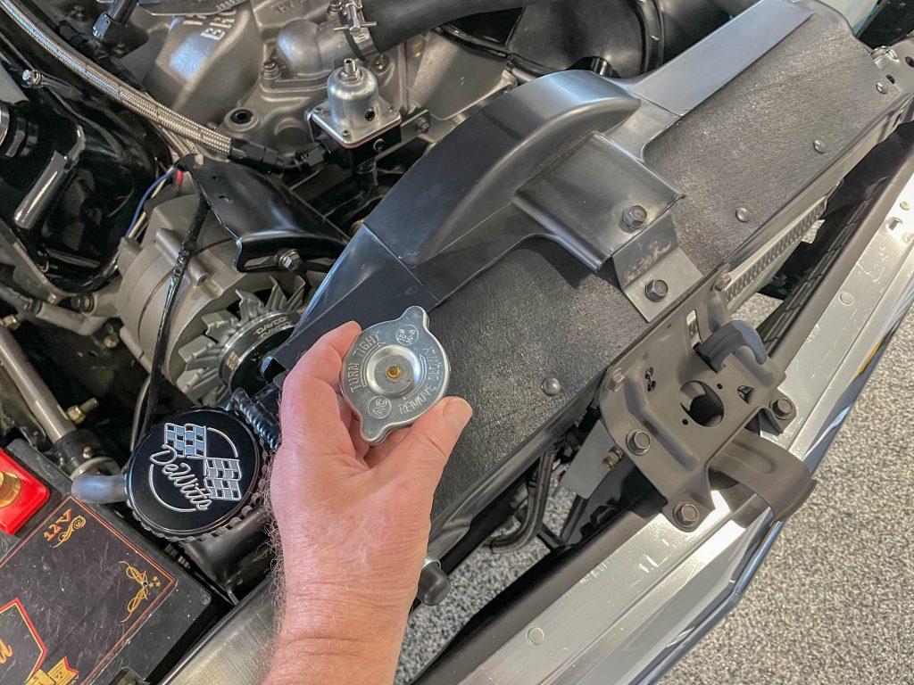
I completely removed the cap and for the first time actually examined it closely. As it turns out, there’s zero evidence of it ever seating on the rad neck. That meant the radiator was never pressurized. Typically, each pound of pressure in the system will raise the boiling point by three degrees. So, in theory, the boiling point should be 257 degrees. Mine clearly didn’t work that way!
The solution for me was to simply re-install the DeWitts radiator cap. To test it, I ran the car outside in 90+ degree ambient temperatures, and well-protected from any wind (basically with the nose of the car up against a closed garage door). I let it idle and watched the temp gauge. This simulates what could very well be the worst possible conditions.
You could see the cooling system cycle through the thermostat opening and closing points. It slowly crept up to 195 and then dropped back to 180 and started the process all over again. Keep in mind the thermostat determines the low end of the temperature operating range. The high end of the operating range is dependent upon the cooling capacity of the radiator and fan. In my case, the radiator wasn’t overly hot. No coolant was spewing out of the overflow.
Everything was very much normal. It really turned out to be my Eureka moment!
How an Engine’s Cooling System Works
Before we go any further, let’s take a minute and examine how a typical cooling system works.
Coolant follows a path that really starts at the water pump. The impeller in the water pump draws coolant from the bottom of the radiator (by way of the lower rad hose) and forces it into the cylinder block. As coolant flows through the water jackets, heat is absorbed from the engine before it encounters the thermostat. The thermostat is simply a valve that measures the temperature of the coolant and at a pre-set temperature, opens, allowing hot coolant to enter the radiator.
Once released by the thermostat, hot coolant travels through the upper rad hose into the radiator. The coolant then passes through thin tubes in the radiator where it’s cooled by air flowing over the outside of the tubes. Airflow through the radiator is provided by the car’s velocity along with the cooling fan(s). As the temperature of the coolant increases, so does the pressure within the cooling system.
This pressure is regulated by the radiator cap. Increasing the cooling system pressure raises the boiling point of the coolant. As mentioned above, each pound of increased pressure raises the boiling point by three degrees F. Should the pressure build up higher than the pre-set number for the cap, a spring-loaded valve in the cap is designed to release the pressure.
You might find the next part interesting.
In my case—even with a potentially troublesome hot-headed big block—there’s no real fancy hardware in the cooling combination. As mentioned above I rely upon a quality aluminum radiator (complete with the correct cap!), mounted in an OEM-style big block radiator support, an OEM-style radiator shroud, a stock five blade OEM-style fan (without a clutch, as big block Novas have no room for one), an Edelbrock water pump without a bypass, OEM pulleys, OEM-style hoses and an EMP/Stewart high flow thermostat in a stock housing. The automatic transmission is cooled by a separate Earl’s cooler. I use straight water laced with Water Wetter.
As you can see, the strategy was to rely upon simple, proven parts. Here’s how the key components break down:
10 Key Engine Cooling System Components to Inspect
***
1. Water Pump
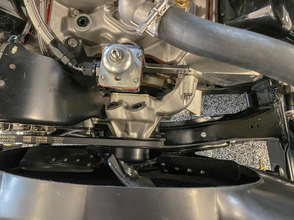
A quality water pump such as the Edelbrock I use is really the heart of the cooling system. Internally, all water pumps incorporate an impeller (with fan-like blades) that spins. This creates centrifugal force, drawing coolant from the rad and moving that coolant into the cylinder block. A critical feature found in high performance pumps is the design of the impeller.
For example, my Edelbrock pump has a large cast iron impeller configuration that is totally CNC machined. Unlike stamped steel pieces, the iron impeller is considerably stronger (and more accurate). Compared to some other pumps, the impeller design found in the Edelbrock pump flows as much as 20 percent more coolant at a much higher pressure. At high RPM, this produces less cavitation that in turn, allows for more equal coolant flow throughout the engine. Additionally, the Edelbrock pump has superior flow balance when compared to a stock pump. This means it will reduce bank-to-bank temperature variances. Increased coolant flow, equal pressure and superior side to side balance means the pump doesn’t need to be turned as quickly in order to achieve the same flow (when compared to say, a factory HD pump).
***
2. Water Pump Bypass
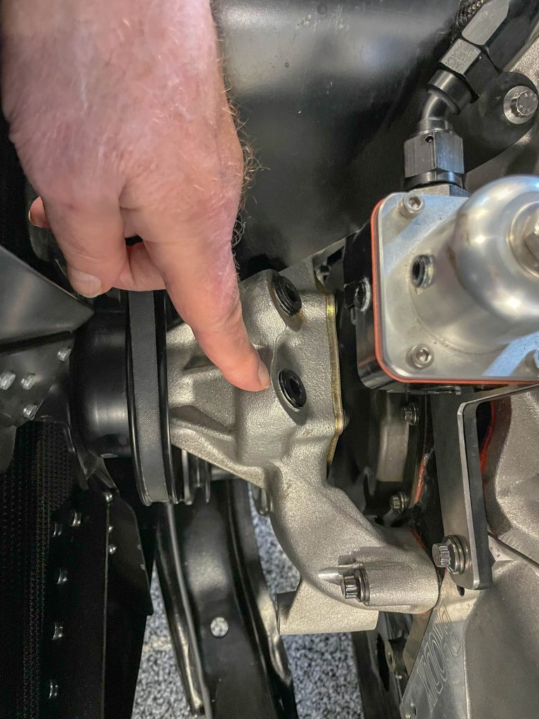
Engines with thermostats typically need some type of bypass arrangement between the water pump and the engine. The idea here is to provide for quick warm up and to prevent pump cavitation. This also tends to minimize steam pocket build-up and, with that, localized water jacket hot spots.
On something like a small block Chevy, the pump bypass is internal. But on a big block, a hose links the top of the water pump to the intake manifold. Many intake manifolds for big blocks do not have the bypass hole drilled and tapped (although some come with an un-machined boss). It is possible to drill and tap the boss and install a bypass hose. But there are a couple of solutions: For a race application, a water restrictor can be used in place of the thermostat. Basically, the restrictor slows down the coolant flow. This is the reason most race-style intake manifolds are not machined for the bypass.
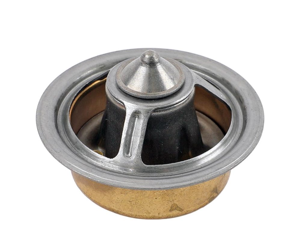
The other solution is to use a thermostat with holes drilled in the flange area. For example, the high flow EMP/Stewart thermostat I use has three 3/16 inch bypass holes machined in it. These three holes work just as efficiently (if not more so) as a bypass hose.
***
3. Radiator Support

What does the rad support have to do with this? Simple. Many cars have radiator supports dedicated to the type and size of the radiator used. For example, my Nova was originally a six-cylinder car. The rad support for a six (and a small block) is built with a smaller opening than a comparable big block car. It also positions the radiator differently. If you attempt to squeeze a big block rad in place, it will be partially blocked by the support and obviously, positioned in the wrong spot. Sure you can hack up a rad support to work but it’s just a whole lot easier to use the right support for the radiator.
***
4. Radiator
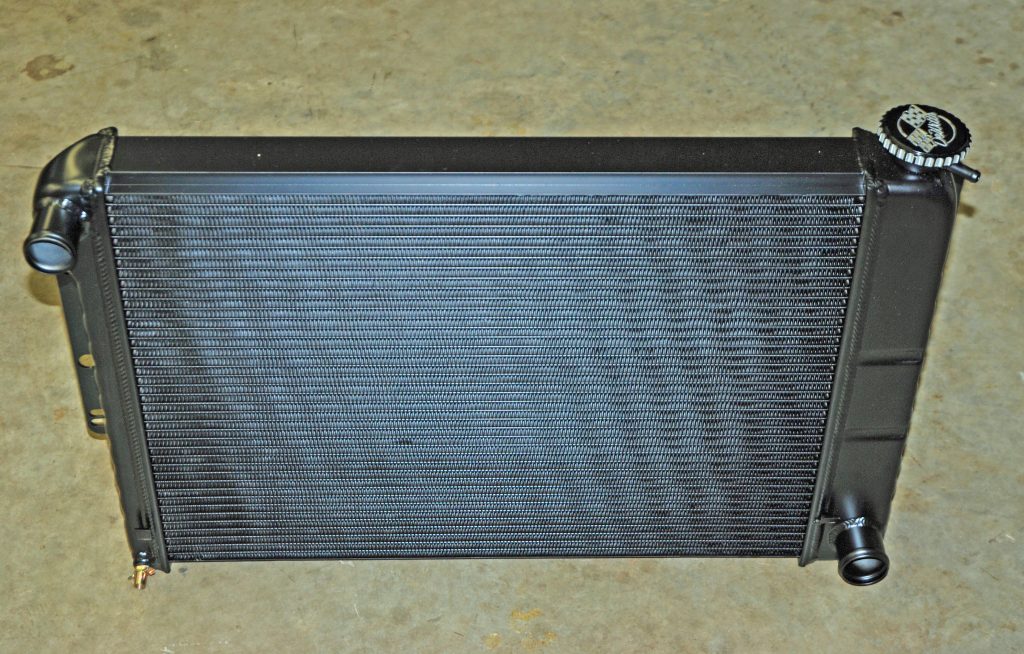
I’m a big fan of modern aluminum radiator construction. Yes, copper is a good material for radiators. It has better heat dissipating properties than aluminum. But according to DeWitts, there are a couple of caveats.
For example, the primary source of cooling in any radiator is the tubes. Heat dissipates from the coolant through the tube walls. This heat is then transferred to the fins that are in contact with the tubes. In turn, this provides a secondary source of cooling. As air passes through the fins, the heat is carried away. Radiator manufacturers know that wider tubes are more efficient because there is more tube-to-fin contact (in a typical modern aluminum radiator, the tube-to-fin contact surface area is increased by 20 percent over an identically sized copper/brass unit—part of this is due to the fact the fins are both wider and closer together with a shorter fin height than a copper radiator). That improved tube-to-fin contact is what removes heat.
But that’s not the end of it. DeWitts tells us that while copper has better thermal conductive properties than aluminum, older copper radiators are made up of four different materials, not just copper. The copper tubes are bonded to the fin with solder (lead) and that has very (Very) poor heat transfer properties. The tanks are made of brass and the side channels are steel.
According to DeWitts: A double row core with one inch tubes is equal to a four row copper unit and almost double the heat rejection of a single row aluminum unit. So, in most cases larger tubes are not necessary (although it is possible, and some manufacturers offer it).
Increasing tube size isn’t always possible with a copper-brass design, because of tube wall thickness limitations. Today’s radiator technology (which typically uses wider tubes inside aluminum rads coupled with multi-louvered fins) has allowed the aluminum radiator to cool efficiently. Just as important, aluminum rads are now as strong, if not stronger than their older copper-brass relatives.
Sure you can build a copper radiator the exact same way high tech aluminum models are constructed. And yes, and it might even work a bit better than the aluminum. The downside is, it would also weigh about 90 pounds! .
The truth is, today, an aluminum radiator in your high performance street car or racecar will simply cool better. Tests from various sources document a 28 percent increase in performance over a brass-copper equivalent, provided both radiators are identical in size. In the end, high-quality aluminum radiator construction can lower engine temperature by as much as 30 degrees.
***
5. Fan Shroud
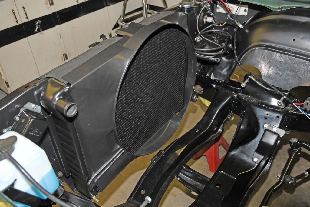
A well designed, properly functioning fan shroud is critical. Properly functioning is the key. I use a reproduction OEM style fan shroud on my car. It’s a tight-fitting example that seals and covers the entire face of the radiator.
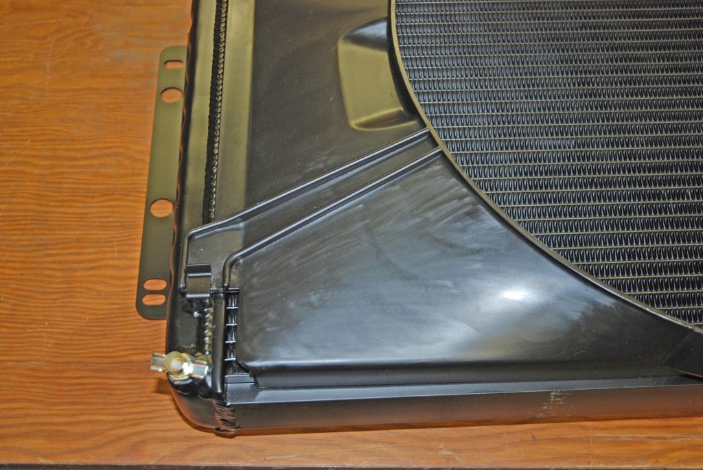
The top and the bottom of the shroud are both tightly secured as well. This means the shroud stays in place at all times. There is no easy escape of air from the top, bottom, or sides.
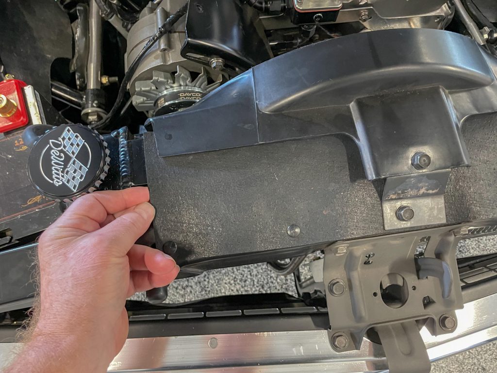
The key here is that all air forced through the radiator from vehicle velocity along with all air drawn through the rad by the fan must pass through the radiator core.
***
6. Fan
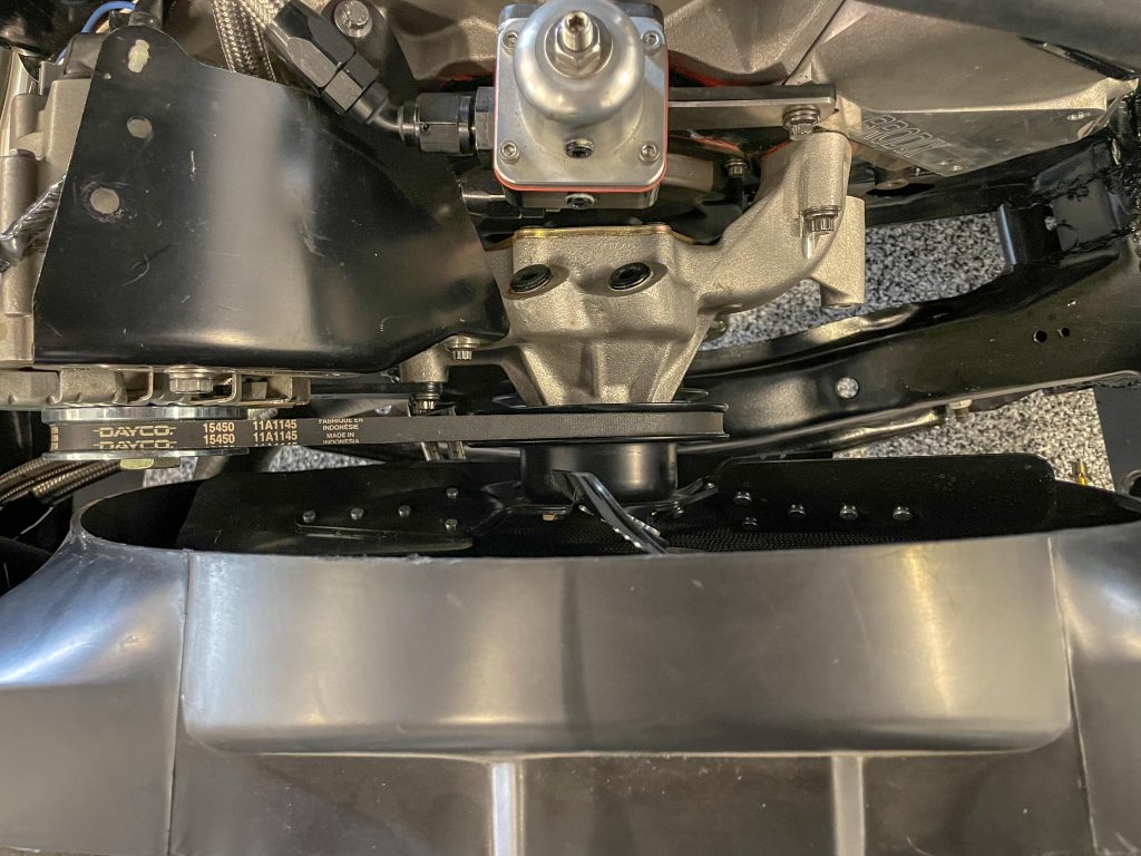
I’m not using a fancy fan either. The mechanical fan for my car is a simple five blade affair that is identical to the fan Chevrolet used on 396 Novas. An interesting point for some is that big block Novas did not incorporate a fan clutch or a fan spacer. Why not? Simple. There is no room between the water pump and the radiator for those items. On the other hand, the fan is positioned relatively tight to the shroud and approximately half of the blade is inside the shroud.
***
7. Pulleys & Hoses
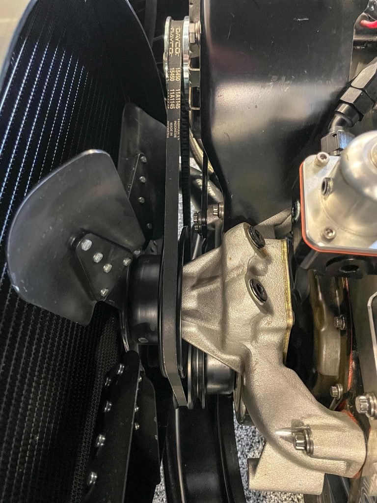
In my case, I use a stock 396-375 HP crank pulley, a stock 396-375 HP water pump pulley, and a stock 396-375 HP alternator pulley (slightly larger than stock). The pulleys are driven by way of a very conventional Dayco v-belt. I simply made certain the pulleys were aligned, and the belt was the correct width and depth (there are some differences out there). Obviously, keeping the belt(s) properly tightened is important too.
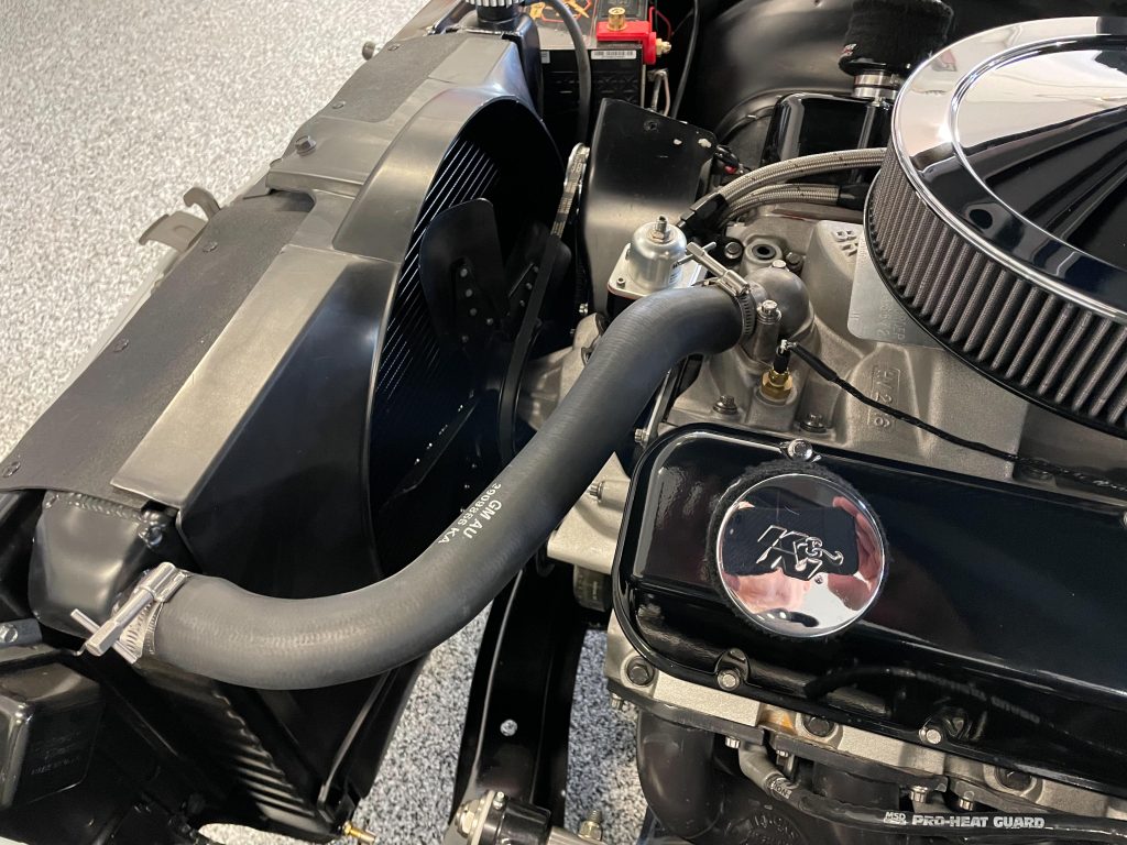
As far as hoses are concerned, I use replacement OEM style hoses, again for a stock 396 Nova. These are formed hoses with an internal wire reinforcement in the bottom hose. Corrugated “fits-all” hoses are something to avoid, as they tend to reduce coolant flow.
***
8. Transmission Cooler
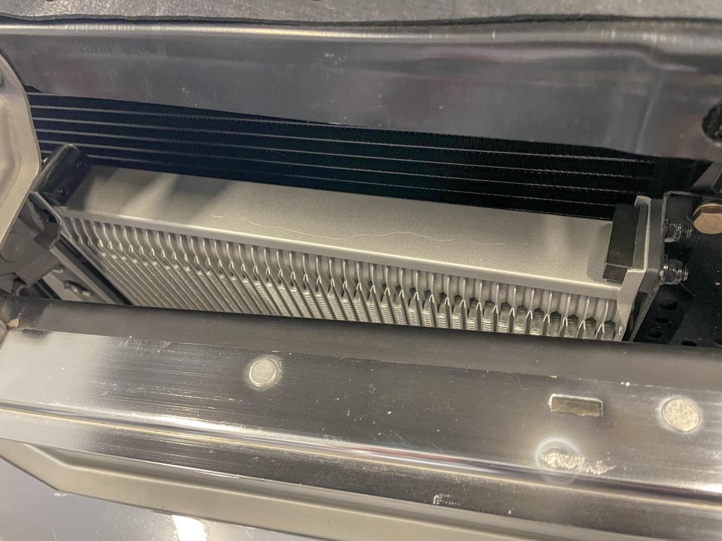
The type and location of the transmission cooler plays a pretty big role in engine coolant temperatures. Automatic transmissions can operate at rather high temperatures, especially if they’re not cooled properly. Keep in mind a small diameter converter will tend to increase transmission fluid temps.
According to ATI:
“In stock applications, a transmission operating at 150 to 175 degrees F, offering a service life of 100,000 miles, has its range cut in half when the temperature increases to 200 degrees. At 295 degrees, service life falls to only 1,500 miles! In specific terms, varnishes form at 240 degrees, seals and sealing rings begin to harden at 260 degrees, and friction plate slippage is unavoidable by 295 degrees. At 350 degrees, all seals and clutches totally burn out and conventional fluid solidifies to form carbon.”
The point here is, a conventional radiator with a built-in transmission cooler doesn’t have adequate capability to cool the transmission fluid in high performance application. In fact, engine coolant temps can increase because of a heavily taxed built-in cooler.
So what’s the solution? Simple. In my case I use a big standalone Earl’s Performance fluid cooler. It’s mounted ahead of the rad (with a gap between the rad and the cooler). Air is obviously forced through it, but it doesn’t have much of an effect upon the capability of the engine radiator. There are a number of other fluid coolers at SummitRacing.com, including coolers with their own dedicated fans.
***
9. Coolant
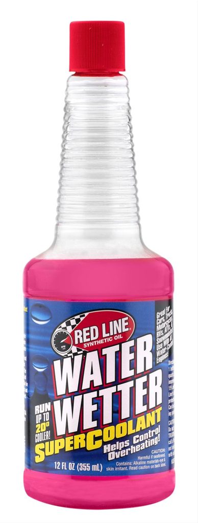
Antifreeze or engine coolant helps to increase the boiling point (when compared to plain water). It also lubricates the water pump and tends to prevent rust and sediment build up. Fair enough, but you can’t use antifreeze if you frequent a drag strip regularly. The reason of course is, it’s a royal pain to clean up if your car leaks. It’s also an even bigger pain if your engine springs an internal gasket leak.
There are plenty of alternatives (various additives that function with tap water), but something like Red Line Oil’s “Water Wetter” work rather well. According to Red Line Oil, water alone has great cooling capability, but it also has very high surface tension. This makes it difficult to release water vapor from the metal surfaces.
Enter additives such as Water Wetter. These additives lower the surface tension of the coolant. This allows for better heat transfer between the engine’s water jackets to the coolant. They also provide for internal corrosion inhibition and provide lubrication for things like the water pump. I use it and it definitely seems to work.
***
10. Ignition Timing
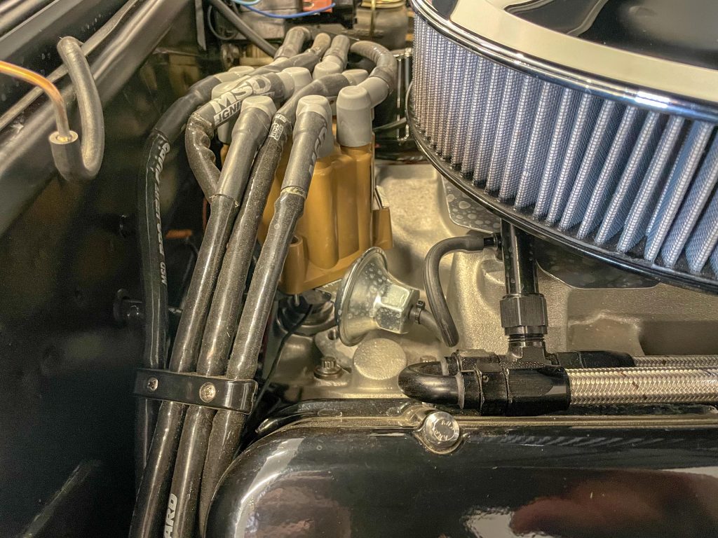
I run my big block with anywhere between 12 and 15 degrees of initial timing. Less initial usually makes them run warm. Something else I do (and some might scoff at this) is to run the engine with an operational vacuum advance system. It does not hurt performance—and it can help to keep the engine temperature under control.
Keep in mind as you whack the throttle, manifold vacuum advance goes away. Vacuum advance only functions during periods of high manifold vacuum and you control it with an adjustable vacuum advance canister. The distributor isn’t getting any extra advance at large throttle inputs.
Bottom line here is, without the vacuum advance hooked up, the engine tends to run hotter.
***
And there it is. That’s my not-so-trick cooling system. It works to cool a pretty healthy siamesed bore 565ci big block inside what amounts to a tight engine compartment at ambient temperatures exceeding 90 degrees F.
I hope there’s something here that you can apply to your own hot ride.

Your article touched on all the major points of cooling. Two areas needs additional comments. My 1970 Chevelle SS, 396 historically had a heat problem. Over the years, (15 years last month) I’ve tried pretty much all the options, additions, and gadgets. Aluminum radiator, fans (5 & 7 blade) with clutch, added two auxiliary fans, smaller carbs, advance timing 34-36, 180 TS.
A friend suggested I relocate the temperature sensor from the head back to the TS housing. This will give you a more general reading of the system. In researching this further, GM had a plan in ’68 to begin relocating the TS from the housing to the head. They started with small blocks and a few other engines. Never really got to the BBC.
One night I remembered an article about alternator pulley diameter. They need approximately 3:1. This got me thinking about the water pump pulley. As it turns out my crank was 6.75″ diameter and the pump was 7.13″. Less than one revolution! Found another GM article, they have 4 sets of pulleys. One for AC and non AC cars, high idle time cars, and racing. My non AC car was set up for racing by GM. At high rpms they didn’t want to overrun the water pump.
I installed an AC water pump pulley at 5.875″ diameter. Pump rpm increased by 152 at idle. I can now run at 180 at an 85 degree day. On cooler days, I’ll run 160 and my auxiliary fans won’t turn on.
Many mechanics have worked on my car. None were able to figure out the solution.
Hope this sheds some light in helping others.
I wanted to express my thanks to Wayne Scraba and Dave Klaas for sharing their knowledge and experiences on classic car cooling issues. Especially Dave Klaas sharing his cooling fix by using smaller diameter 5.875 inch water pump pulley. My next classic car buy and my current classic car 65 El Camino 350/320 HP, the crankshaft pulley diameter will be/is 6.75 inch, will have the 5.875 inch water pump pulley installed. Makes perfect sense reduce water pump pulley size to increase the crankshaft water pump ratio gaining more water pump/fan rpm to fix overheating issues during high idle times. Thanks a $Million for sharing.