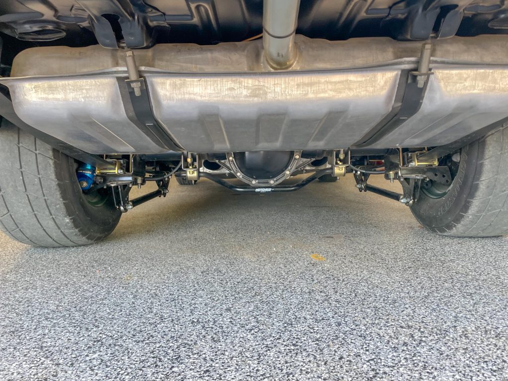
In Part 1 of Hidden Assets, we covered the design and installation basics of Holley’s HydraMat fuel pickup system. Now I’ll show you how I installed one in the gas tank of my big block-powered 1969 Nova. It isn’t a hard process, but it does require some planning and patience. Let’s get to it.
The Tank
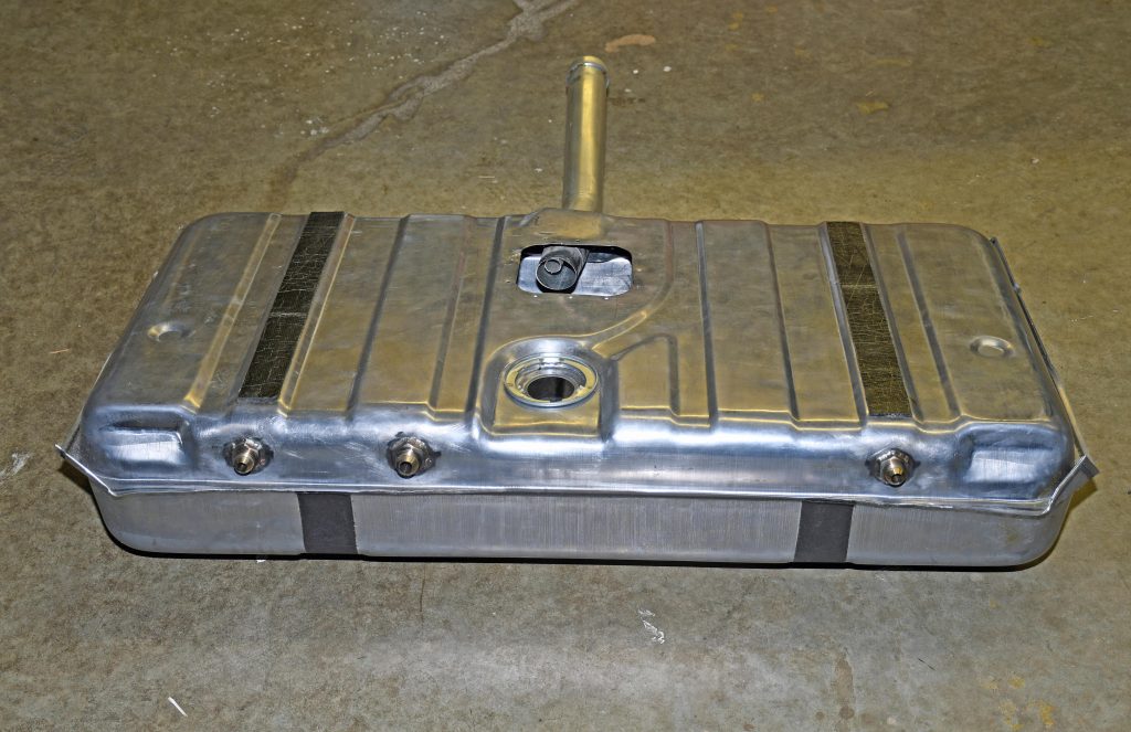
The process began with selecting a new gas tank. I chose a steel tank that is a dead ringer for a production line tank. Summit Racing offers one from Auto Metal Direct that is virtually identical to mine. The gameplan here was to build a fuel delivery system that wasn’t visible on the outside of the car. This isn’t my first rodeo at building a tank with hidden pickups, but it was definitely my first attempt using a HydraMat as the basis for the fuel system.
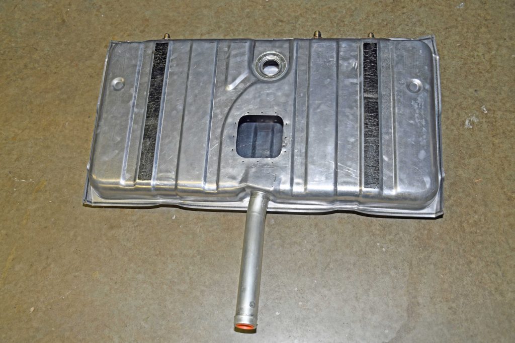
I spent quite a bit of time determining how to get the big 15 x 15 inch square HydraMat in the tank. It was clearly much too large to fit through the sender hole in the tank–my forearm won’t even. Besides, I needed plenty of room to access and install the pickup and return plumbing along with an external high flow vent.
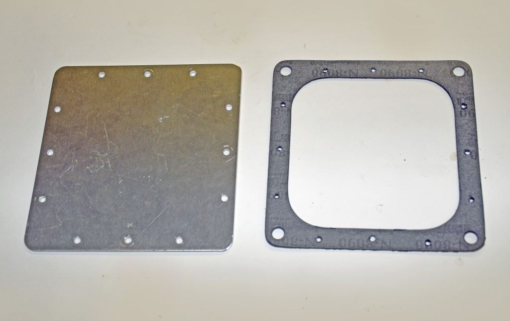
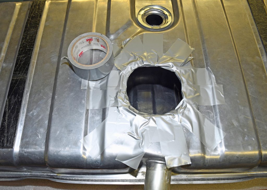
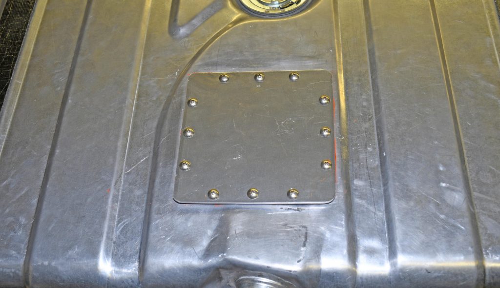
My solution was pretty simple: cut an access hole in the top of the tank and seal it with piece of metal and a fuel-safe gasket of some sort. I used a baseplate gasket for a Holley 4500 Series Dominator carburetor to do this. The inside dimension is sufficiently large that I can reach inside the tank to hook up the fittings, center the HydraMat, etc. I used the gasket as a template to cut a hole in the top of the gas tank and to make a cover plate out of 0.090-inch thick aluminum. I drilled a series of mounting holes around the outer edges for mounting screws.
Tank Fittings
I mounted the fittings for the pickup, pump return line, and vent near the top of the tank on the forward wall. It’s possible to do this because the external fuel pump I used (a Weldon A600 from Summit Racing) is designed to pull a prime. It’s no different than a stock tank arrangement where a mechanical fuel pump draws fuel out of the top of the tank from the pickup in the sender assembly. The idea won’t work if your fuel pump needs to be gravity fed.
I used a -10AN stainless steel bulkhead fitting for the feed line and -8 AN stainless fittings for the return and vent lines. Installation consisted of cutting appropriately sized holes with hole saws, adding a set of stainless bulkhead nuts on the inside to retain the fittings, and then TIG welding the bulkheads to the outside body of the tank. Cutting and modifying the tank for the bulkheads and the access panel didn’t take that long. On the other hand, cleaning the filings out of the inside of the tank was pure drudgery.
Some may question the need for a vent line, but I use one. A stock system which doesn’t move huge volumes of fuel relies on a tiny hole in the gas cap for venting. Novas and other cars with low-mounted filler necks and vented gas caps are notorious for spewing gas out the back when you get on the throttle. By using a separate high-capacity vent and a non-vented gas cap, my car doesn’t gush raw gas out the back on acceleration.
Installing the HydraMat
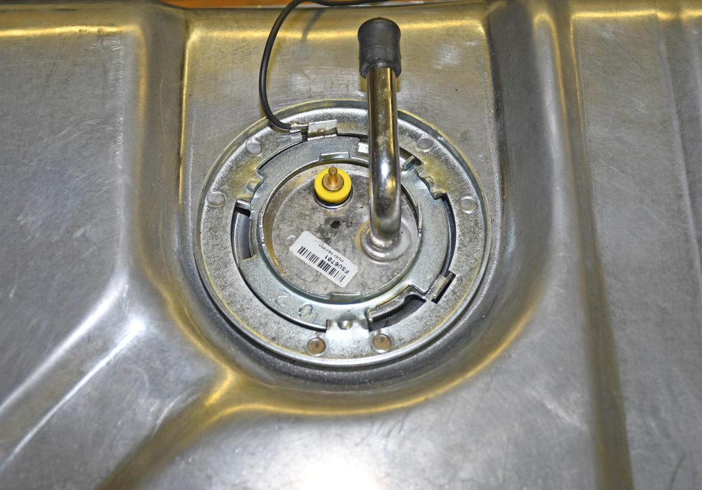
The HydraMat replaces the sending unit assembly as a fuel pickup, but I needed the sender to activate the fuel gauge. I modified it by cutting off the original fuel pickup tube from the sender assembly and capping the line. The float and sending unit still function as normal so the gas gauge works.
If you try this for your tank, keep the location of the sender and the float in mind when figuring out where to place the HydraMat. Given the float location, I mounted mine slightly offset to the passenger side rear of the gas tank. This ensures the sender float doesn’t get tangled up with the fuel pickup line at the top of the HydraMat.
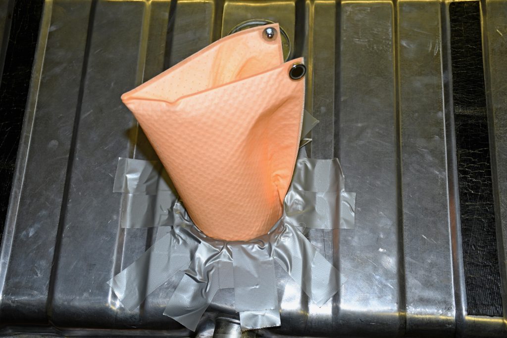
Installing the HydraMat inside the tank was next. I rolled it into a tube shape and carefully inserted through the access hole in the top of the gas tank. I taped off the edges of the with a lot of duct tape so the relatively sharp edges of the opening wouldn’t slice the HydraMat—or my arm. You can unfurl the HydraMat once it’s in the tank and adjust the location by hand.
As mentioned in Part 1, the HydraMat is held in place with rare earth magnets on each corner. I chose to install the magnets before it was installed inside the tank. I think it’s easier than installing them after it’s inside–you might be surprised at how tenacious four little magnets can be. I did use a big wooden dowel to slowly coax the HydraMat into place.
Fuel Line Plumbing
My setup requires two fuel lines inside the tank–one for the fuel pickup and one for the fuel return. You must use fuel-safe hose for both of them.
My HydraMat has a large 1/2-inch NPT fitting (most are smaller). The feed line runs from that to the -10 AN bulkhead fitting. That required a length of 5/8-inch diameter hose. There aren’t a lot of options for hose that size that can live submersed in gasoline, so I used Tygon tubing. It’s a yellowish flexible plastic hose that is compatible with most fuels, including those that contain alcohol.
(EDITORS NOTE: Summit Racing offers Pacific Coast Engineering (PPE) submersible fuel hose in 5/8-inch diameter that will work for carbureted applications).
The return line was made using 1/2-inch Tygon tubing. I directed the return line away from the fuel pickup point. It’s also a good idea to keep it submerged in fuel if possible. If it’s left wide open, the spray raises havoc with the gas in the tank, basically aerating the fuel supply.
I used Earl’s Performance Super Stock Hose Ends for the pickup and return lines. They have a barb end that is pushed into the hose. I secured the hose to the fittings with a pair of stainless steel hose clamps on each end. Here are the fittings I used:
• Pickup Line: 90-degree -10 AN fitting with 1/2-inch to -10 AN adapter at the HydraMat outlet, -10 AN straight fitting at the bulkhead
• Return Line: straight -8 AN fitting at the bulkhead
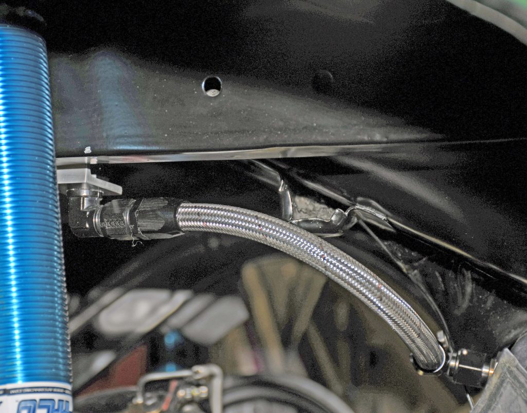
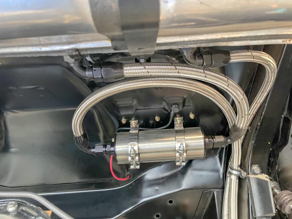
The supply (feed) line from the tank to the Weldon electric fuel pump is -10 AN stainless braided hose. The return line from the pressure regulator is -8 AN hose. Because the HydraMat acts as a prefilter (before the pump), you only need a fuel filter after the pump. I used a big Holley HP Billet Fuel Filter.
With all of the lines inside the tank installed and double-checked, I put the top inspection plate on the tank. This setup requires a non-vented cap that fits very tightly on the filler neck. You might have to try a couple of different caps before you find one that fits properly.
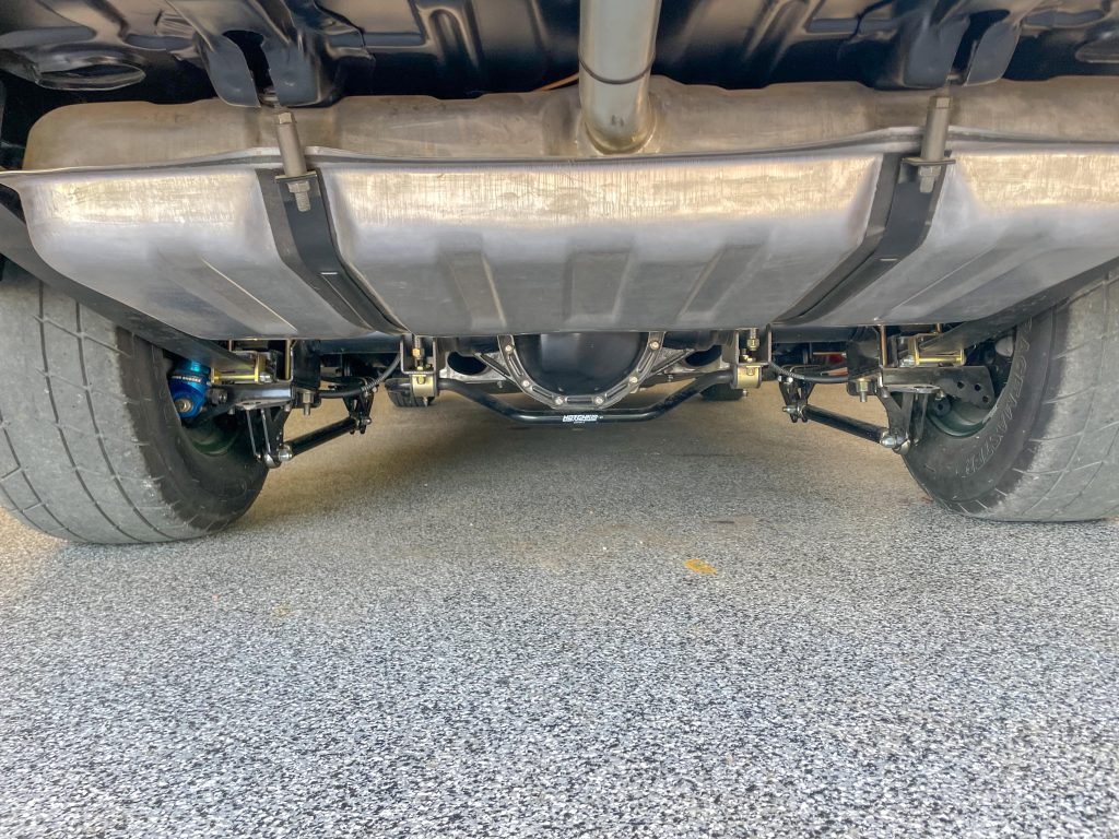
Once complete, the system is all but invisible from the outside. Does it work? As mentioned in that first article, Heck ya! Fuel pressure is absolutely stable throughout the RPM range. It doesn’t spew gas out the back and it’s possible to run the car hard with a quarter-tank of fuel or less. Check out the accompanying photos to see how I did it.
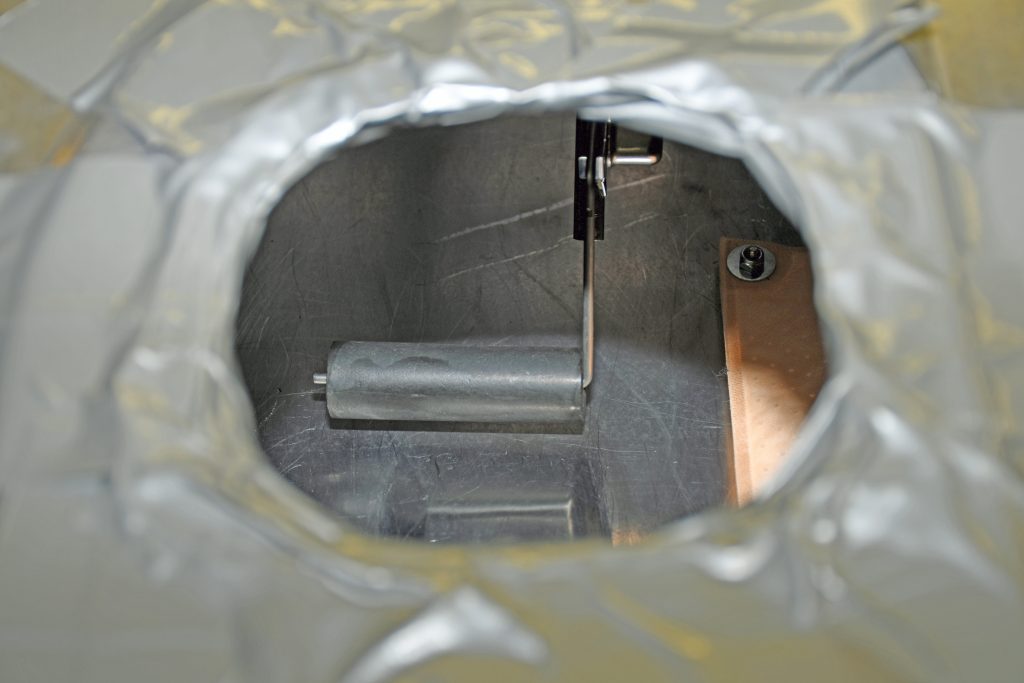
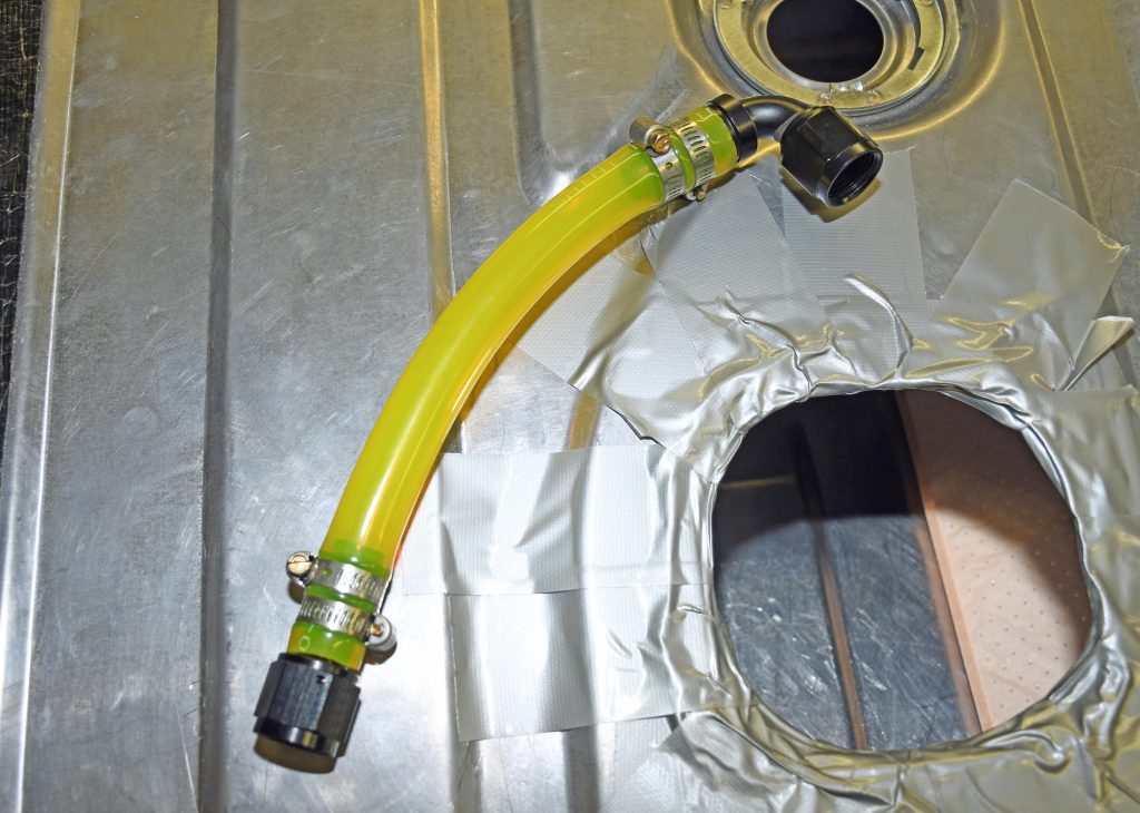
-10 AN Earl’s Super Stock fittings. The hose was secured to the tubing with double stainless steel hose clamps on each end. The -8 AN return line uses 1/2-inch tubing and one Super Stock fitting. The line simply lays on the tank floor. (Image/Wayne Scraba)

Comments